Trane Liqui-Flo Addendum Instruction Manual D2-3415
The information in this manual is subject to change without notice. Throughout this manual, the following notes are used to alert you to safety considerations: ! ATTENTION: Identifies information about practices or circumstances that can lead to personal injury or death, property damage, or economic loss. Important: Identifies information that is critical for successful application and understanding of the product.
CONTENTS Chapter 1 Introduction 1.1 Intended Audience........................................................................................... 1-1 1.2 Other Required Manuals ................................................................................. 1-1 Chapter 2 About the Drive and Cabinet 2.1 Identifying the Trane Model Number ............................................................... 2-1 2.2 Enclosure Rating .................................................................................
II Trane Liqui-Flo Addendum
List of Figures Figure 2.1 – Identifying the Trane Model Number .................................................... 2-1 Figure 2.2 – Trane Cabinet Component Locations (6-Pulse Rectifier) ..................... 2-3 Figure 2.3 – Trane Cabinet Component Locations (12-Pulse Rectifier) ................... 2-5 Figure 3.1 – Cabinet Dimensions ............................................................................. 3-2 Figure 3.2 – Cabinet Mounting Holes ........................................................
IV Trane Liqui-Flo Addendum
List of Tables Table 2.1 – Power and Enclosure Ratings ............................................................... 2-2 Table 3.1 – Cabinet Dimensions............................................................................... 3-1 Table 3.2 – Cabinet Mounting Hole Dimensions ...................................................... 3-1 Table 5.1 – Hardware Tightening Torques ............................................................... 5-3 Table 5.2 – C-Frame Liqui-Flo Drive Replacement Parts..........
VI Trane Liqui-Flo Addendum
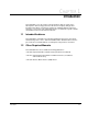
CHAPTER 1 Introduction This addendum covers the features and specifications that are unique to the AC Liqui-Flo drives being produced for the Trane Company. Only product information that differs from that presented in the standard Liqui-Flo instruction manuals is covered here. This addendum must be used with the Liqui-Flo software and hardware instruction manuals listed below. 1.
1-2 Trane Liqui-Flo Addendum
CHAPTER 2 About the Drive and Cabinet This chapter describes how to identify the Trane cabinet and the Liqui-Flo drive using the Trane model number matrix. Liqui-Flo drive power ratings are listed as well as available Trane options. Cabinet component drawings are also provided. Note that in this manual references to the “cabinet” refer to both the 6-pulse and 12-pulse rectifier cabinets, unless otherwise indicated. 2.
Table 2.1 – Power and Enclosure Ratings Trane Cabinet M/N AFDB0643GA0A10 2.2 Reliance Liqui-Flo Drive M/N 64L4060 Frame Size C Cabinet Enclosure Rating NEMA 1 Input Power (KVA) 555 Input Current (Amps) 667 Output Current at 2 kHz (Amps) 643 Full Load Power Loss Watts 9500 Enclosure Rating The Trane cabinet has a NEMA 1 enclosure rating: • NEMA 1: Vented. Intended for general-purpose indoor applications.
24 1 25 T2 T1 9 T6 T4 T3 2 T5 10 3 11 4 12 5 13 14 15A 15A 2A 15 30A 6 7 10A 16 8a 8b 17 18 19 20 21 23 22 Front View Figure 2.
The 12-pulse rectifier Trane cabinets have the following main components. The identification numbers provided correspond to the numbers used in figure 2.3. 1. 2. 3. 4. 5. 6. 7. 8. 9. 10. 11. 12. 13. 14. 15. 16. 17. 18. 19. 20. 21. 22. 23. 24. 25. 26. 27.
1 26 27 T1 10 T2 T3 2 11 T6 T4 T5 3 12 4 13 5 14 6 15 16 15A 17 7 15A 2A 30A 10A 8 18 9a 19 9b 20 21 22 23 25 24 Front View Figure 2.
2.4 Trane Options There is one available Trane option, the 12-pulse rectifier cabinet, which is described in this addendum. Note that all Trane Liqui-Flo drives have a factory-installed Remote Meter Interface (RMI) board and meet California code regulations.
CHAPTER 3 Cabinet Mounting, Wire Routing, and Liquid-Cooling Connections This chapter provides cabinet dimension information that must be considered when installing a Trane cabinet. It describes how to mount the Trane cabinet and shows where the wire entry areas and liquid-cooling connection points are located. 3.1 Planning the Cabinet Installation Cabinet dimensions and weights are listed in table 3.1. Overall cabinet dimensions are illustrated in figure 3.1. Cabinet mounting holes are shown in figure 3.
C A E D B F Figure 3.
3/8" Screws, 4 Pl. (Inside Cabinet) E F (3 Pl.) D A 1/2" Screws, 4 Pl. B G C Figure 3.
3.3 Cabinet Wire Routing All wiring should be installed in conformance with the applicable local, national, and international codes (for example, NEC/CEC). Figures 3.3 and 3.4 show the wire routing, grounding terminal, and power terminal strips of the cabinet. Control wiring enters the cabinet through the three holes on the left side and terminates at the control panel’s terminal block. Tighten the control wire connections from 7.1 to 8.9 in-lb. 3.
Top View 3-Phase AC Voltage Enters 127.0 mm (5.0") Recommended, 3 Pl. Cabinet Here 3-Phase AC Volts Input to Line Side of Circuit Breaker T1 T6 T2 T4 T3 T5 3-Phase AC Volts Output to Motor Ground Stud Connections (Left Side Wall) 28.58 mm (1.125") 15A 15A 2A Signal Control Wiring Enters 22.23 mm (0.875") 2 Pl. 30A 10A Cabinet Here Signal Control Wiring Coolant Bulkhead Fittings Side View Front View Figure 3.
111.1 mm (4.38") Recommended, 8 Pl. Top View 127.0 mm (5.0") Recommended, 3 Pl. 3-Phase AC Volt Output from Load Side of Circuit Breaker to Primary of Delta-Wye Transformer T1 T6 T2 T4 T3 T5 from Secondary of Delta-Wye Transformer (6 Places) Ground Stud Connections (Left Side Wall) 3-Phase AC Volt Input to 3-Phase AC Volts Output to Line Side of Circuit Breaker Motor 28.58 mm (1.125") 15A 15A 2A Signal Control Wiring Enters 22.23 mm (0.875") 2 Pl.
Step 3. Use a wrench to further tighten the connectors 1.5 to 2.5 turns. Do not hold the bulkhead fitting with a pipe wrench when tightening the connectors as the fitting may be damaged. Note that the bulkhead fitting has a built-in anti-rotation feature and will not turn as the connector is screwed in. ! ATTENTION: The cabinet’s bulkhead fittings may be damaged if they are held with a pipewrench. Do not hold the bulkhead fitting with a pipe wrench when tightening the connectors.
SAE 37× Swivel Nut, Thread Size 7/8-14 Hex Nut Drive Side Lock Washer Flat Washer Double-D Anti-Rotation Feature Between the Bulkhead Fitting and Main Panel Assembly Main Panel Assembly Bulkhead Fitting @ Rear of Cabinet 1-11 1/2 NPTF - Dryseal American Standard Taper Pipe Thread (SAE J476) Chiller Side Tubing Connection from Trane-Supplied Heat Exchanger / Pump Assembly Figure 3.
CHAPTER 4 Connecting Cabinet Power Wiring This chapter describes how to connect input and output power to the cabinet. 4.1 Cabinet Input Disconnect ! ATTENTION: The user is responsible for conforming with all applicable local, national, and international codes. Failure to observe this precaution could result in damage to, or destruction of, the equipment. An input disconnect circuit breaker is factory-installed in the cabinet.
AC Input 3-Phase 380/480 V L1 L2 L3 On-Site Connections Will Accept Four 3/0 To 400 MCM/Phase (Copper Conductors Only) Circuit Breaker R S T On-Site Ground Connection Will Accept Two 4/0 to 350 MCM (Copper Conductors Only) Liqui-Flo AC Drive U V W Flexibar 8x40x1 T1 T6 T2 T4 T3 Inside Cabinet Trane-Supplied Connections T5 Motor Figure 4.
4.3 Installing Input Power Wiring (12-Pulse Rectifier Cabinet) ! ATTENTION: The user is responsible for conforming with all applicable local, national, and international codes. Failure to observe this precaution could result in damage to, or destruction of, the equipment. Use the following steps to connect AC input power to the cabinet: Step 1. Remove the top panel of the cabinet. Important: Care must be taken to prevent debris from falling into the cabinet while performing this installation. Step 2.
AC Input 3-Phase 380/480 V L1 L2 On-Site Connections Will Accept Four 3/0 To 400 MCM/Phase (Copper Conductors Only) L3 Inside Cabinet Circuit Breaker R S T On-Site Connections Will Accept Four 3/0 To 400 MCM/Phase (Copper Conductors Only) On-Site Ground Connection Will Accept Two 4/0 To 350 MCM (Copper Conductors Only) Transformer On-Site Connections Will Accept Two 6 AWG To 250 MCM/Phase (Copper Conductors Only) S1 S2 S3 S4 S5 S6 Liqui-Flo Inside Cabinet AC Drive U V T1 W T2 Flexibar 8x
4.4 Installing Output Power Wiring ! ATTENTION: The user is responsible for conforming with all applicable local, national, and international codes. Failure to observe this precaution could result in damage to, or destruction of, the equipment. Use the following steps to connect the cabinet’s output power wiring from the Liqui-Flo drive to the chiller motor: Step 1.
4-6 Trane Liqui-Flo Addendum
CHAPTER 5 Cabinet Servicing This chapter describes how to remove the Liqui-Flo drive from the cabinet and provides a list of replacement parts. 5.1 Removing the Liqui-Flo Drive from the Cabinet Follow the procedure in section 5.1.1 if you are removing a Liqui-Flo drive from a 6-pulse rectifier cabinet. Follow the procedure in section 5.1.2 if you are removing a Liqui-Flo drive from a 12-pulse rectifier cabinet. 5.1.
Step 6. Disconnect the Flexibar conductors at the drive’s U, V, and W output terminals. a. Remove the two 3/8”-16-UNC-2B nuts from the clamp holding the Flexibar to the AC output busbar at output terminals U, V, and W. b. Remove the load plate and the clamps. c. Save this hardware for reassembly. Step 7. Remove the rigid buswork that connects the load side of the circuit breaker to the drive. a. Remove the 1/12”-13 bolts and washers from each of the drive’s AC input terminals (L1 through L6). b.
Step 16. Using the hoist, lift the drive slightly to take the load off of the cabinet’s panel studs. Pull the drive off of the studs and up through the wire entry and access panels until it is clear of the cabinet enclosure. Note that drive’s center of gravity is forward of the hoist, which will result in the top of the drive tilting forward during removal. Step 17. Move the drive to a horizontal pallet for servicing or shipment. The eyebolts and the chain between them do not need to be removed. Step 18.
b. Connect one end of a drain hose to the accumulator on the closed loop coolant system. Connect the other end of the hose to a drain. c. Connect a shop air line to the closed loop coolant system at the quick disconnect fitting. Pressurize the line to 60-90 psi for 1 to 2 minutes to flush all of the coolant out of the drive. d. Remove the basket from the Y-strainer and check for any contaminants. e.
Step 14. Using an overhead or portable hoist (minimum 1/2 ton rated capacity), attach a free-fall chain to the 1.5” hole in the support bar. Take up any vertical slack in the chain. Step 15. Vertically lift the support bar and the drive 3” to 4”. a. Rotate the support bar to the right side, towards you, and slip the support bar/drive assembly out of the cabinet. Step 16. Move the drive to a horizontal pallet for servicing or shipment. The support bar and screws do not need to be removed. Step 17.
5.2 Replacement Parts Table 5.2 lists the replacement parts that are available from Reliance Electric. Table 5.
INDEX A F Air ventilation, 3-1 Audience, intended, 1-1 Fan, 2-2 to 2-5, 5-6 Fuses, 2-2 to 2-5 G B Grounding, 3-4 Board Bus Control, 2-2 to 2-5 Power Module Adapter (PMA), 2-2 to 2-5 Regulator, 2-2 to 2-5 Remote Meter Interface, 2-2 to 2-5 H C I Cabinet dimensions, 3-1 to 3-2 electrical connections, 4-2, 4-4 grounding, 3-4 to 3-6 mounting, 3-1 to 3-3 weight, 3-1 wire routing, 3-4 to 3-6 Component locations, 2-2 to 2-5 Input current rating, 2-2 Input disconnect, 4-1 Input power rating, 2-2 Installati
M T Model numbers Trane, 2-1 Reliance, 2-2 Mounting dimensions, 3-1 to 3-2 U N V NEMA enclosure, 2-2 W O Options, Trane, 2-6 Output current rating, 2-2 P Planning, cabinet installation, 3-1 Power wiring, 4-1 to 4-5 input, 4-1 to 4-4 output, 4-5 sizes, 4-2, 4-4 Publications, related, 1-1 Watts loss rating, 2-2 Weight, cabinet, 3-1 Wire routing, 3-4 to 3-6 sizes, 4-2, 4-4 Wiring diagrams, A-1 to A-2 X Y Q Z R Ratings input, 2-2 output, 2-2 power loss, 2-2 Regulator board, 2-2 to 2-3, 4-5 Replacemen
U.S. Drives Technical Support Tel: (1) 262.512.8176, Fax: (1) 262.512.2222, Email: support@drives.ra.rockwell.com, Online: www.ab.com/support/abdrives Publication D2-3415-July 1998 Copyright © 1998 Rockwell Automation, Inc. All Rights Reserved. Printed in USA.