
Instruction Manual

Installation/Wiring
2-11
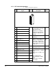
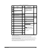
2.5.2 Encoder Terminal Block
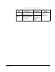
Table 2.3 – Encoder Terminal Designations
No. Description
8
+12V
1
DC Power
1.
Jumper selectable +5/12V is available on 20B-ENC-2 Encoder Boards only.
Internal power
source
250 mA.
7 +12V<Footnote>(1) DC
Return (Common)
6 Encoder Z (NOT) Pulse, marker or
registration
input.
2
2.
Z channel can be used as a pulse input while A & B are used for encoder.
5 Encoder Z
4 Encoder B (NOT) Quadrature B
input.
3 Encoder B
2 Encoder A (NOT) Single channel
or quadrature A
input.
1 Encoder A
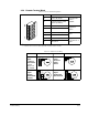
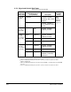
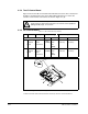
Table 2.4 – Sample Encoder Wiring
I/O Connection Example I/O Connection Example
Encoder
Power
–
1
Internal
Drive Power
Internal
(drive) 12V
DC, 250mA
1.
SHLD connection is on drive chassis.
Encoder
Power
–External
Power
Source
Encoder
Signal
–Single-
Ended, Dual
Channel
Encoder
Signal
–Differential,
Dual Channel
8
1
Common
+12V DC
(250 mA)
1
2
3
4
5
6
7
8
to SHLD
+
Common
External
Power
Supply
to
SHLD
B
B NOT
A NOT
A
Z
Z NOT
to SHLD
to Power Supply
Common
1
2
3
4
5
6
7
8
to SHLD
1
2
3
4
5
6
7
8
B
Z
A NOT
B NOT
Z NOT
A