
Instruction Manual


2-4
DBT Reach Drive User Manual
2.2.1 Safety Ground - PE
This is the safety ground for the drive that is required by code. This point must be
connected to adjacent building steel (girder, joist), a floor ground rod or bus bar (see
above). Grounding points must comply with national and local industrial safety
regulations and/or electrical codes.
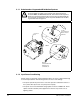
2.2.2 Shield Termination - SHLD
The Shield terminal provides a grounding point for the motor cable shield. The motor
cable shield should be connected to this terminal on the drive (drive end) and the
motor frame (motor end). A shield terminating cable gland may also be used.
When shielded cable is used for control and signal wiring, the shield should be
grounded at the source end only, not at the drive end.
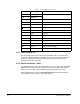
Table 2.1 – Power Termination Locations Notes
Terminal Description Notes
BR1 DC Brake (+) DB Resistor Connection
BR2 DC Brake (-)
DC+ DC Bus (+)
DC- DC Bus (-)
PE PE Ground
Motor Ground
U U (T1) To motor
V V (T2) To motor
W W (T3) To motor
R R (L1) AC Line Input Power
S S (L2) AC Line Input Power
T T (L3) AC Line Input Power
PS+ AUX (+) Auxiliary Control Voltage
PS- AUX (-) Auxiliary Control Voltage