Reach Drive User Manual Manufactured for DBT Instruction Manual D2-3561
The information in this manual is subject to change without notice. Throughout this manual, the following notes are used to alert you to safety considerations: ! ATTENTION: Identifies information about practices or circumstances that can lead to personal injury or death, property damage, or economic loss. Important: Identifies information that is critical for successful application and understanding of the product.
CONTENTS Chapter 1 Introduction 1.1 Who Should Use this Manual? ........................................................................ 1-1 1.2 Manual Conventions ........................................................................................ 1-1 1.3 Identifying the Drive by Nameplate.................................................................. 1-1 1.4 Identifying the Drive by Model Number ........................................................... 1-2 Chapter 2 Installation/Wiring 2.
Appendix A Technical Specifications........................................................................................... A-1 Appendix B Logic Command/Status Words ................................................................................ B-1 Appendix C HIM Overview........................................................................................................... C-1 Appendix D Application Notes ..............................................................................................
CHAPTER 1 Introduction The purpose of this manual is to provide you with the basic information needed to install, start-up, and troubleshoot the Reach Drive. 1.1 Who Should Use this Manual? This manual is intended for qualified personnel. You must be able to program and operate adjustable frequency AC drives devices. In addition, you must have an understanding of the parameter settings and functions. 1.
1.4 Identifying the Drive by Model Number Each Reach Drive and Reach Drive Kit can be identified by its model number. The model number is on the shipping label and drive nameplate. The model number includes the drive and any factory-installed options. Table 1.
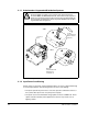
CHAPTER 2 Installation/Wiring This chapter provides information on mounting and wiring the Reach Drive. Most start-up difficulties are the result of incorrect wiring. Every precaution must be taken to assure that the wiring is done as instructed. All items must be read and understood before the actual installation begins ! 2.1 ATTENTION: The following information is merely a guide for proper installation.
2.1.1 Unbalanced or Ungrounded Distribution Systems ! ATTENTION: Power distribution to Reach Drives is intended to be from the ungrounded secondary of the system’s step down transformer. Protective MOVs, the EMI Snubber Board, and common mode capacitors (3 places) in the drive have been disconnected. They should typically be reconnected in any application where the power distribution at the drive is grounded. Refer to Figure 2.
• The power source has frequent interruptions. If these conditions exist, it is recommended that the user install a minimum amount of impedance between the drive and the source. This impedance could come from the supply transformer itself, the cable between the transformer and drive or an additional transformer or reactor. 2.2 General Grounding Requirements The drive Safety Ground - PE must be connected to system ground.
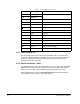
Table 2.1 – Power Termination Locations Notes Terminal Description BR1 DC Brake (+) BR2 DC Brake (-) DC+ DC Bus (+) DC- DC Bus (-) PE PE Ground Notes DB Resistor Connection Motor Ground U U (T1) To motor V V (T2) To motor W W (T3) To motor R R (L1) AC Line Input Power S S (L2) AC Line Input Power T T (L3) AC Line Input Power PS+ AUX (+) Auxiliary Control Voltage PS- AUX (-) Auxiliary Control Voltage 2.2.
2.2.3 RFI Filter Grounding Using an optional RFI filter may result in relatively high ground leakage currents. Therefore, the filter must only be used in installations with grounded AC supply systems and be permanently installed and solidly grounded (bonded) to the building power distribution ground. Ensure that the incoming supply neutral is solidly connected (bonded) to the same building power distribution ground.
2.4.3 Power Termination Location Notes (-) DC BUS TEST POINT (+) DC BUS TEST POINT Figure 2.3 – Power Termination Locations (DC+ and DC-) BR1 BR2 Figure 2.
R S T Figure 2.5 – Power Termination Locations (U, V, W, R, S, T) 2.5 I/O Wiring Important points to remember about I/O wiring: • Use Copper wire only. Wire gauge requirements and recommendations are based on 75 degrees C. Do not reduce wire gauge when using higher temperature wire. • Wire with an insulation rating of 600V or greater is recommended. • Control and signal wires should be separated from power wires by at least 0.3 meters (1 foot).
2.5.1 I/O Terminal Designations Table 2.2 – I/O Terminal Designations No. Signal Factory Default Description Rel. Param. 1 16 2-8 1 Analog In 1 (-)1 2 Analog In 1 (+)1 3 Analog In 2 (-)1 4 Analog In 2 (+)1 5 32 320327 2 Isolated3, bipolar, differential +/- 10V/4-20mA, 11 bit and sign, 88k ohm input impedance. For 4-20mA, a jumper must be installed at terminals 17 and 18 (or 19 and 20). Port Common - For (+) and (-) 10V port references.
Table 2.2 – I/O Terminal Designations No. 17 18 19 20 Signal Factory Default Description Rel. Param. Placing a jumper across terminals 17 and 18 (or 19 and 20) will configure that analog input for current. (Parameter 320 must be set ON.) Current In Jumper1 - Analog In 1 Current In Jumper1 – Analog In 2 21 –10V Pot Reference – 2k ohm minimum load. 22 +10V Pot Reference – 23 HW PTC Input 1 – See above 24 +24VDC 5 – Drive supplied logic input power.
32 POSITION I/O PLUG REMOVE FROM CONTROL PCB TERMINATE WIRE HARNESS TO PLUG THEN MATE PLUG TO HEADER AND FASTEN SCREWS TO 7 in-lbs SCREW ON PLUG NUT ON PCB HEADER Figure 2.
2.5.2 Encoder Terminal Block Table 2.3 – Encoder Terminal Designations No. 8 1 Description 8 +12V 1 DC Power 7 +12V(1) DC Return (Common) 6 Encoder Z (NOT) 5 Encoder Z 4 Encoder B (NOT) 3 Encoder B 2 Encoder A (NOT) 1 Encoder A 1. Jumper selectable +5/12V is available on 20B-ENC-2 Encoder Boards only. 2. Z channel can be used as a pulse input while A & B are used for encoder. Internal power source 250 mA. Pulse, marker or registration input. 2 Quadrature B input.
2.5.3 Signal and Control Wire Types Table 2.5 – Recommended Signal Wire Signal Type/ Where Used Analog I/O and PTC Belden Wire Type(s) (or equivalent) Description 8760/9460 0.750 mm2 (18AWG), twisted pair, 100% shield with drain1 . 8770 0.750 mm2 (18AWG), 3 cond., shielded for remote pot only. Encoder/ Pulse I/O <30 m (100 ft.) Combined: 97302 0.196 mm2 (24AWG), individually shielded. Encoder/ Pulse I/O 30 to 152 m (100 to 500 ft.) Signal: 9730/97282 0.196 mm2 (24AWG), individually shielded.
Table 2.6 – Recommended Control Wire for Digital I/O Type Installation/Wiring Wire Type(s) Description Unshielded Per US NEC or applicable – national or local code Shielded Multi-conductor shielded cable such as Belden 8770(or equiv.) 0.750 mm2 (18AWG), 3 conductor, shielded.
2.5.4 The I/O Control Board Figure 2.2 shows the I/O control board and terminal block locations. The control board provides a mounting point for the various Reach Drive I/O options. To remove the cassette, loosen the two screw latches as shown in Figure 2.7. (A). ! ATTENTION: You must stay within the minimum and maximum wire size range. Failure to observe this precaution can result in severe equipment damage, bodily injury, or loss of life. 2.5.5 I/O Terminal Blocks Table 2.
2.5.6 Hardware Enable Circuitry By default, the user can program a digital input as an Enable input. The status of this input is interpreted by drive software. If the application requires the drive to be disabled without software interpretation, a “dedicated” hardware enable configuration can be utilized. This is done by removing a jumper and wiring the enable input to “Digital In 6.” (See tables 2.5 and 2.6 for more information). 1. Remove the I/O Control board. 2.
PIN 1 PIN 1 PIN 6 PIN 12 RTD PC BOARD RTD PC BOARD ASSEMBLED IN ENCLOSURE Figure 2.
2.5.7.1 Connections 24 Mode Time 13 12 7 Gain 12 1 2 3 1 2 3 S1 S2 6 1 J2 - RTD Inputs 1 J3 - I/O J2 Figure 2.9 – RTD Board Connections Table 2.
RTD/NTC Sourcing A 2-wire RTD or NTC temperature sensor may be used. A chassis connection is available for each sensor for use with shielded cable. Each channel requires up to three connections. Multiplexer and Amplifier An analog multiplexer sequentially connects the temperature sensors one at a time to the analog output. The active sensor channel is indicated by a 3-bit output (A0-A2). When using an RTD or NTC, a simple voltage divider is formed and the device is probed differentially.
Example: Using a 100 Ohm Pt RTD (a=0.00385) to measure temperatures from 0 degrees Celsius to 200 degrees Celsius, the maximum resistance occurs at 200 degrees Celsius and is approximately 177 Ohm. The maximum voltage across the sensor is 151 mV. If the x40 gain is used, the output voltage at 200 degrees Celsius is 6.04 Volts. 4th Order Low Pass Filter FC = 16Hz MAX4194 Instrumentation Amp Rail-to-Rail Gain Adjustable 5V F 12V SA (1 of 8) 12V 10 F DA Analog Out 0-10V 0.
When the “Mode” switch is up (open) the board uses the digital input as an enable/reset. When the board’s digital input is inactive (open or ground), the analog output is held at the first channel. When the digital input is active (24V), the microcontroller sequentially cycles through the eight temperature sensor channels. Each channel is available at the analog output for the selected period of time. After the eighth channel is completed, the cycle begins again with the first channel.
CHAPTER 3 Parameter Descriptions The following information is provided for each parameter along with its description: Parameter Number: Unique number assigned to each parameter. Parameter Name: Unique name assigned to each parameter. Range: Predefined parameter limits or selections. Note that a negative Hz value indicates reverse rotation. Default: Factory default setting. Access: Parameter access level.
3.1 Parameters 1 Output Freq Range: +/-400.0 Hz [0.1 Hz] Default: Read Only Access: 0 Path: Monitor>Metering See also: The output frequency present at T1, T2, and T3 (U, V, and W). 2 Commanded Speed Range: +/- [P.082 Maximum Speed] [0.1 Hz or 0.1 RPM] Default: Read Only Access: 0 See also: 79 Path: Monitor>Metering The value of the active Speed/Frequency Reference. Displayed in Hz or RPM, depending on value of Speed Units (79). 3 Output Current Range: 0.0 to Drive Rated Amps x 2 [0.
6 Output Voltage Range: 0.0 to Drive Rated Volts [0.1 VAC] Default: Read Only Access: 0 Path: Monitor>Metering See also: The output voltage present at terminals T1, T2, and T3 (U, V, and W). 7 Output Power Range: 0 to Drive Rated kW x 2 [0.1 kW] Default: Read Only Access: 0 Path: Monitor>Metering See also: The output power present at T1, T2, and T3 (U, V, and W). 8 Output Powr Fctr Range: 0.00 to 1.00 [0.
11 MOP Reference Range: +/- [Maximum Speed] [0.1 Hz or 0.1 RPM] Default: Read Only Access: 1 See also: 79 Path: Monitor>Metering The value of the signal at the MOP (Motor-Operated Potentiometer). 12 DC Bus Voltage Range: 0 to Based on Drive Rating [0.1 VDC] Default: Read Only Access: 1 Path: Monitor>Metering See also: The present DC bus voltage level. 13 DC Bus Memory Range: 0 to Based on Drive Rating [0.
18 PTC HW Value Range: 0.00 to 5.00 Volts [0.01 Volts] Default: Read Only Access: 2 Path: Monitor>Metering See also: This parameter displays the value present at the drive’s PTC input terminals. When a motor is provided with a PTC (positive temperature coefficient) thermal sensor, it can be connected to terminals 10 and 23.
24 FV Commanded Torque Range: +/- 800.0% Default: Read Only Access: 0 See also: 53 [0.1%] Path: Monitor>Metering The final torque reference value after limits and filtering are applied. Percent of motor rated torque. 25 Speed Feedback Range: +/- 400.0 Hz or +/- 24,000.0 RPM [0.1 Hz or 0.1 RPM] Default: Read Only Access: 1 Path: Monitor>Metering See also: Displays the lightly filtered value of the actual motor speed based on measured encoder feedback or an estimation.
The drive rated output current. 29 Control SW Ver Range: 0.000 to 65535.000 [0.001] Default: Read Only Access: 0 See also: 196 Path: Monitor>Drive Data The Main Control board software version. 40 Motor Type Range: 0 = Induction 1 = Synchr Reluc 2 = Synchr PM Default: 0 = Induction Access: 2 See also: 53, 157, 158, 159 Path: Motor Control>Motor Data Set to match the type of motor connected: Induction, Synchronous Reluctance, or Synchronous Permanent Magnet.
43 Motor NP Hertz Range: 5.0 to 400.0 Hz [0.1 Hz] Default: Based on Drive Type Access: 1 Path: Motor Control>Motor Data See also: Set to the motor nameplate rated frequency. The motor nameplate base frequency defines the output frequency when operating at rated voltage, rated current, rated speed, and rated temperature. 44 Motor NP RPM Range: 60.0 to 25200.0 RPM [0.1 RPM] Default: 1780 RPM Access: 1 Path: Motor Control>Motor Data See also: Set to the motor nameplate rated RPM.
47 Motor OL Hertz Range: 0.0 to Motor NP Hz [0.1 Hz] Default: Motor NP Hz/3 Access: 2 See also: 42, 220 Path: Motor Control>Motor Data Selects the output frequency below which the motor operating current is derated. The motor thermal overload will then generate a fault at lower levels of current. 48 Motor OL Factor Range: 0.20 to 2.00 [0.1] Default: 1.00 Access: 2 See also: 42, 220 Path: Motor Control>Motor Data Sets the amps threshold for motor overload fault.
SV Economize = Allows the drive to automatically adjust output voltage as the load changes to minimize current supplied to the motor. The voltage is adjusted by means of flux current adaptation. Custom V/Hz = Allows the user to tailor the volts/hertz curve by adjusting parameters Maximum Voltage (54), Maximum Frequency (55), Run Boost (70), Break Voltage (71) and Break Frequency (72).
Allowable Output Frequency Range Bus Regulation or Current Limit Allowable Output Frequency Range - Normal Operation Allowable Speed Reference Range V Max Volts o (54) l t Motor Volts a (41) g e Frequency Trim due to Speed Control Mode Overspeed Limit (83) Break Volts (71) Start Boost (69) Run Boost (70) 0 Min Speed (81) Break Frequency (72) Motor NP Hz (43) Frequency Max Speed (82) Output Freq Limit Maximum Freq (55) Figure 3.1 – Speed Limits 56 Compensation Range: See figure 3.
Enable Jerk = Enables/disables the jerk limit in the current limiter that helps to eliminate overcurrent trips on fast accelerations. Disable this feature if your application requires the actual acceleration of the motor to be faster than .25 sec. In non-FVC Vector modes, disabling jerk removes a short S-curve at the start of the accel/decel ramp. Ixo AutoCalc = Reserved Xsistor Diag = Enables/disables power transistor power diagnostic tests that execute at each Start command.
61 Autotune Range: 0 = Ready 1 = Static Tune 2 = Rotate Tune 3 = Calculate Default: 3 = Calculate Access: 1 See also: 53, 62 Path: Motor Control>Torq Attributes Provides a manual or automatic method for setting IR Voltage Drop (62), Flux Current Ref (63) and Ixo Voltage Drop (64). Valid only when Motor Cntl Sel (53) is set to Sensrls Vect, SV Economize or FVC Vector. Ready (0) = Parameter returns to this setting following a Static Tune or Rotate Tune.
62 IR Voltage Drop Range: 0.0 to Motor NP Volts x 0.25 [0.1 VAC] Default: Based on Drive Rating Access: 1 See also: 53, 61 Path: Motor Control>Torq Attributes Value of volts dropped across the resistance of the motor stator. Used only when Motor Cntl Sel (53) is set to Sensrls Vect, SV Economize or FVC Vector. 63 Flux Current Ref Range: 0.00 to Motor NP FLA [0.
67 FV Inertia Autotune Range: 0 = Ready 1 = Inertia Tune Default: 0 = Ready Access: 1 See also: 53, 450 Path: Motor Control>Torq Attributes Provides an automatic method of setting Total Inertia. This test is automatically run during Start-Up motor tests. Important: Use when motor is coupled to the load. Results may not be valid if the load is not coupled to the motor during this procedure. Ready = Parameter returns to this setting following a completed inertia tune.
72 Break Frequency Range: 0.0 to Maximum Freq [0.1 Hz] Default: Motor NP Freq x 0.25 Access: 2 See also: 53, 71 Path: Motor Control>Volts per Hertz Sets the frequency the drive will output at Break Voltage (71). 79 Speed Units Range: 0 = Hz 1 = RPM 2 = Convert Hz 3 = Convert RPM Default: 0 = Hz Access: 0 Path: Speed Command>Spd Mode & Limits See also: Selects the units to be used for all speed related parameters. Options 0 and 1 indicate status only.
! ATTENTION: When operating the drive with encoder feedback selected (Feedback Select (80) = 3 (Encoder)), a loss of encoder signal may produce an overspeed condition. For differential encoders, Motor Fdbk Type (412) should be selected as option 1 or 3 to detect the loss of an encoder signal. The user is responsible for ensuring that the driven machinery, all drive-train mechanisms, and application material are capable of safe operation at the maximum operating speed of the drive.
ATTENTION: The user is responsible for ensuring that the driven machinery, all drive-train mechanisms, and application material are capable of safe operation at the maximum operating speed of the drive. Overspeed detection in the drive determines when the drive shuts down. The factory default for overspeed detection is set to 10.0 Hz (or 300.0 RPM) greater than the Maximum Speed (82). Failure to observe this precaution could result in equipment damage, sever injury or loss of life.
84 85 86 Skip Frequency 1 Skip Frequency 2 Skip Frequency 3 Range: -/+ Maximum Speed [0.1 Hz] Default: 0.0 Hz Access: 2 See also: 87 Path: Speed Command>Spd Mode & Limits Sets a frequency at which the drive will not operate (also called an avoidance frequency). Requires that both Skip Frequency 1-3 and Skip Frequency Band (87) be set to a value other than 0. 87 Skip Freq Band Range: 0.0 to 30.0 Hz [0.1 Hz] Default: 0.
Speed Reg (1) = Drive operates as a speed regulator. Torque Reg (2) = An external torque reference is used for the torque command. Min Torq/Spd (3) = Selects the smallest algebraic value to regulate to when the torque reference and torque generated from the speed regulator are compared. Max Torq/Spd (4) = Selects the largest algebraic value to regulate to when the torque reference and torque generated from the speed regulator are compared.
! ATTENTION: Changing parameter 89 to Terminal Blk or Network while Start At PowerUp is enabled may start the drive if a start command is on from the newly selected logic source. When Start At PowerUp is enabled, the user must ensure that automatic start up of the driven equipment will not cause injury to operating personnel or damage to the driven equipment.
Selects the source of the speed reference to the drive unless Preset Speed 1-7 (101-107) or Speed Ref B (93) is selected. Note that the manual reference command and input HIM Control can override the reference control source. ! 91 ATTENTION: Removing and replacing the LCD HIM while the drive is running may cause an abrupt speed change if the LCD HIM is the selected reference source.
93 Speed Ref B Sel Range: 1 = Analog In 1 2 = Analog In 2 3-6 = Reserved 7 = Pulse In 8 = Encoder 9 = MOP Level 10 = Reserved 11 = Preset Spd 1 12 = Preset Spd 2 13 = Preset Spd 3 14 = Preset Spd 4 15 = Preset Spd 5 16 = Preset Spd 6 17 = Preset Spd 7 18 = Local HIM 19 = DPI Port 2 20 = DPI Port 3 21 = DPI Port 4 22 = Network 23-24 = Reserved 25 = Scale Block 1 26 = Scale Block 2 27 = Scale Block 3 28 = Scale Block 4 Default: 11 = Preset Spd 1 Access: 0 See also: 2, 91-93, 101-107, 117-120, 192-194,
94 Speed Ref B Hi Range: -/+Maximum Speed [0.1 Hz or 0.01 RPM] Default: Maximum Speed Access: 1 See also: 79, 93, 190 Path: Speed Command>Speed References Scales the upper value of the Speed Ref B Sel (93) selection when the source is an analog input. 95 Speed Ref B Lo Range: -/+Maximum Speed [0.1 Hz or 0.01 RPM] Default: 0.
98 TB Man Ref Lo Range: -/+Maximum Speed [0.1 Hz or 0.01 RPM] Default: 0.0 Access: 1 See also: 79, 96 Path: Speed Command>Speed References Scales the lower value of the TB Man Ref Sel selection when the source is an analog input. 99 Pulse Input Ref Range: -/+ 400.0 Hz or -/+ 24000.0RPM [0.1 Hz or 0.
Table 3.1 – Default Values for Preset Speeds 1-7 108 Parameter No. Parameter Name Default Access 101 Preset Speed 1 5.0 Hz or 150 RPM 0 102 Preset Speed 2 10.0 Hz or 300 RPM 2 103 Preset Speed 3 20.0 Hz or 600 RPM 2 104 Preset Speed 4 30.0 Hz or 900 RPM 2 105 Preset Speed 5 40.0 Hz or 1200 RPM 2 106 Preset Speed 6 50.0 Hz or 1500 RPM 2 107 Preset Speed 7 60.0 Hz or 1800 RPM 2 Jog Speed 2 Range: -/+ Maximum Speed [0.1 Hz or 0.1 RPM] Default: 10.0 Hz or 300.
117 Trim In Select Range: 0 = Setpoint 1 = Analog In 1 2 = Analog In 2 3-6 = Reserved 7 = Pulse In 8 = Encoder 9 = MOP Level 10 = Reserved 11 = Preset Spd 1 12 = Preset Spd 2 13 = Preset Spd 3 14 = Preset Spd 4 15 = Preset Spd 5 16 = Preset Spd 6 17 = Preset Spd 7 18 = Local HIM 19 = DPI Port 2 20 = DPI Port 3 21 = DPI Port 4 22 = Network 23-24 = Reserved 25 = Scale Block 1 26 = Scale Block 2 27 = Scale Block 3 28 = Scale Block 4 Default: 1 = Analog In 1 Access: 2 See also: 90, 93 Path: Speed Comma
PT C Re HW se DP rved I Mo at 50 to 0 Bu r Ov k s F er Cu req ld rr R Au Lim eg toR it Au st to A DB Rst ct A C Au ctiv tdn toT e DC un B in Sto raki g pp ng Jo ing gg Ru ing nn Ac ing tiv Re e ad y 0 x 0 0 0 0 0 0 0 0 0 0 0 0 0 0 15 14 13 12 11 10 9 8 7 6 5 4 3 2 1 0 1 =Condition True 0 =Condition False x =Reserved Bit # Figure 3.4 – Trim Out Select (118) 119 Trim Hi Range: -/+Maximum Speed [0.1 Hz or 1 RPM/%] Default: 60.
122 Slip Comp Gain Range: 1.0 to 100.0 [0.1] Default: 40.0 Access: 2 See also: 80, 121, 122 Path: Speed Command>Slip Comp Sets the response time of slip compensation. 123 Slip RPM Meter Range: -/+300.0 RPM [0.1 RPM] Default: Read Only Access: 2 See also: 80, 121, 122 Path: Speed Command>Slip Comp Displays the present amount of adjustment being applied as slip compensation. Important: Parameters in the Process PI Group are used to enable and tune the PI Loop.
Bit 1 - Invert Error • Enables/disables the option to invert the sign of the PI error signal. Enabling this feature creates a decrease in output for an increasing error and an increase in output for a decreasing error. Bit 2 - Preload Mode • Enabled = Initializes the PI integrator to the commanded speed while the PI is disabled. • Disabled = The PI integrator is loaded with the PI Pre-load (133) while the PI is disabled.
PI control allows the drive to take a reference signal (setpoint) and an actual signal (feedback) and automatically adjust the speed of the drive to match the actual signal to the reference. Proportional control (P) adjusts the output based on the size of the error (larger error = proportionally larger correction). Integral control (I) adjusts the output based on the duration of the error. The integral control by itself is a ramp output correction.
126 PI Reference Sel Range: 0 = Setpoint 1 = Analog In 1 2 = Analog In 2 3-6 = Reserved 7 = Pulse In 8 = Encoder 9 = MOP Level 10 = Master Ref 11 = Preset Spd 1 12 = Preset Spd 2 13 = Preset Spd 3 14 = Preset Spd 4 15 = Preset Spd 5 16 = Preset Spd 6 17 = Preset Spd 7 18 = Local HIM 19 = DPI Port 2 20 = DPI Port 3 21 = DPI Port 4 22 = Network 23-24 = Reserved 25 = Scale Block 1 26 = Scale Block 2 27 = Scale Block 3 28 = Scale Block 4 Default: 0 = PI Setpoint Access: 2 See also: 124-138 Path: Speed
128 PI Feedback Sel Range: 0 = Setpoint 1 = Analog In 1 2 = Analog In 2 3-6 = Reserved 7 = Pulse In 8 = Encoder 9 = MOP Level 10 = Master Ref 11 = Preset Spd 1 12 = Preset Spd 2 13 = Preset Spd 3 14 = Preset Spd 4 15 = Preset Spd 5 16 = Preset Spd 6 17 = Preset Spd 7 18 = Local HIM 19 = DPI Port 2 20 = DPI Port 3 21 = DPI Port 4 22 = Network 23-24 = Reserved 25 = Scale Block 1 26 = Scale Block 2 27 = Scale Block 3 28 = Scale Block 4 Default: 0 = PI Setpoint Access: 2 See also: 124-138 Path: Speed C
130 PI Prop Gain Range: 0.00 to 100.00 [0.01] Default: 1.00 Access: 2 See also: 124-138 Path: Speed Command>Process PI Sets the value for the PI proportional component when the PI Hold bit of PI Control (125) = Enabled (1). PI Error x PI Prop Gain = PI Output 131 PI Lower Limit Range: -/+400.0 Hz or -/+ 800.0% [0.1 Hz or .01%] Default: -Maximum Freq or -100% Access: 2 See also: 79, 124-138 Path: Speed Command>Process PI Sets the lower limit of the PI output.
Sets the value used to preload the integral component on start or enable. 134 PI Status Range: See figure 3.7 Default: Read Only Access: 2 See also: 124-138 Path: Speed Command>Process PI PI In PI Limi R t PI eset H PI old En ab led The present state of the process PI regulator. x x x x x x x x x x x x 0 0 0 0 15 14 13 12 11 10 9 8 7 6 5 4 3 2 1 0 Nibble 4 Nibble 3 Nibble 2 Nibble 1 Bit # 1 =Condition True 0 =Condition False x =Reserved Figure 3.
136 PI Fdback Meter Range: -/+100.0% [0.1%] Default: Read Only Access: 2 Path: Speed Command>Process PI See also: 124-138 Present value of the PI feedback signal. 137 PI Error Meter Range: -/+200.0% [0.1%] Default: Read Only Access: 2 Path: Speed Command>Process PI See also: 124-138 Present value of the PI error signal. 138 PI Output Meter Range: -/+ 100.0 Hz or -/+ 800.0% [0.1 Hz or 0.
140 141 Accel Time 1 Accel Time 2 Range: 0.0 to 3600.0 [0.1 sec] Default: 10.0 secs Access: 140=0 141=2 See also: 142, 143, 146, 361 Path: Dynamic Control>Ramp Rates The Accel Time parameters set the rate at which the drive ramps to its output frequency after a start command or during an increase in command frequency (speed change).
146 S Curve % Range: 0 to 100% Default: 0% Access: 0 [0.1%] Path: Dynamic Control>Ramp Rates See also: 140 - 143 Sets the percentage of acceleration or deceleration time that is applied to the ramp as S Curve. Time is added; 1/2 at the beginning and 1/2 at the end of the ramp.
150 Drive OL Mode Range: 0 = Disabled 1 = Reduce CLim 2 = Reduce PWM 3 = Both-PWM 1st Default: 3 = Both-PWM 1st Access: 1 See also: 219 Path: Dynamic Control>Load Limits Selects the drive’s response to increasing drive temperature and may reduce the current limit value as well as the PWM frequency. If the drive is being used with a sine wave filter, the filter is likely tuned to a specific carrier frequency.
153 Regen Power Limit Range: -800.0 % to 0.0% Default: -50.0% Access: 1 See also: 53 [0.1%] Path: Dynamic Control>Load Limits Sets the maximum power limit allowed to transfer from the motor to the DC Bus. When using an external dynamic brake, set Regen Power Limit to its maximum value. 154 Current Rate Lim Range: 1.0% to 800.0% Default: 400.0% Access: 1 [0.1%] Path: Dynamic Control>Load Limits See also: Sets the largest allowable rate of change for the current reference signal.
157 DC Brake Lvl Sel Range: 0 = DC Brake Lvl 1 = Analog In 1 2 = Analog In 2 Default: 0 = DC Brake Lvl Access: 1 See also: 155, 156, 158, 159 Path: Dynamic Control>Stop/Brake Modes Selects the source for DC Brake Level (158). 158 DC Brake Level Range: 0 to (Rated Amps x 1.5) [0.1 Amps] Default: Rated Amps x 1.
160 Bus Reg Ki Range: 0 to 5000 [1] Default: 450 Access: 2 See also: 161, 162 Path: Dynamic Control>Stop/Brake Modes Sets the responsiveness of the bus regulator. 161 162 Bus Reg Mode A Bus Reg Mode B Range: 0 = Disabled 1 = Adjust Freq 2 = Dynamic Brak 3 = Both - DB 1st 4 = Both - Frq 1st Default: Mode A: 0 = Disabled Mode B: 0 = Disabled Access: 2 See also: 160, 163 Path: Dynamic Control>Stop/Brake Modes Sets the method and sequence of the DC bus regulator voltage.
! ATTENTION: The adjust freq portion of the bus regulator function is extremely useful for preventing nuisance overvoltage faults resulting from aggressive decelerations, overhauling loads, and eccentric loads. It forces the output frequency to be greater than commanded frequency while the drive’s bus voltage is increasing towards levels that would otherwise cause a fault.
164 Bus Reg Kp Range: 0 to 10000 Default: 1500 Access: 2 Path: Dynamic Control>Stop/Brake Modes See also: Proportional gain for the bus regulator. Used to adjust regulator response. 165 Bus Reg Kd Range: 0 to 10000 Default: 1000 Access: 2 Path: Dynamic Control>Stop/Brake Modes See also: Derivative gain for the bus regulator. Used to control regulator overshoot.
Enables/disables a feature to issue a Start or Run command and automatically resume running at commanded speed after drive input power is restored. When enabled, Start At PowerUp requires a digital input configured and closed for Run or Start and a valid start contact. ATTENTION: Be aware of the following: ! • Setting parameter 168 to 1 (Enabled) immediately applies output power to the motor when all start conditions are met.
174 Auto Rstrt Tries Range: 0 to 9 [1] Default: 0 (Disabled) Access: 1 See also: 175 ! Path: Dynamic Control>Restart Modes ATTENTION: Equipment damage and/or personal injury may result if parameter 174 is used in an inappropriate application. Do not use this function without considering applicable local, national, and international codes, standards, regulations, or industry guidelines.
• Removing the enable input signal. • Setting Auto Restrt Tries to zero. • Occurrence of a fault that is not auto-resettable. • Removing power from the drive. • Exhausting an auto-reset/run cycle. 175 Auto Rstrt Delay Range: 0.5 to 10800.0 sec Default: 1.0 sec Access: 1 See also: 174 [0.1 sec] Path: Dynamic Control>Restart Modes Sets the time between restart attempts when the auto restart feature is enabled. Refer to Auto Rstrt Tries (174) for more information about the auto restart feature.
ATTENTION: Enabling the Sleep-Wake function can cause unexpected machine operation during the Wake mode. Failure to observe these precautions can result in damage to the equipment and/or personal injury. ! Table 3.
181 Wake Time Range: 0.0 to 1000.0 Secs [0.1 sec] Default: 0.0 sec Access: 1 See also: 180 Path: Dynamic Control>Restart Modes Defines the amount of time at or above Wake Level before a start command is issued. 182 Sleep Level Range: 4.000 mA, 0.000 V / Wake Level [0.001 mA, 0.001 V] Default: 5.000 mA, 5.000 V Access: 1 See also: 183 Path: Dynamic Control>Restart Modes Defines the analog input level that will stop the drive. 183 Sleep Time Range: 0.0 to 1000.0 secs [0.
185 Power Loss Timer Range: 0.0 to 60.0 sec [0.1 sec] Default: 0.5 sec Access: 1 See also: 184 Path: Dynamic Control>Power Loss Sets the time that the drive will remain in power loss mode before a fault is issued. 186 Power Loss Level Range: 0.0 to 999.9 [0.1 VDC] Default: Drive Rated Volts Access: 1 Path: Dynamic Control>Power Loss See also: When set to a non-zero value, selects the change in level at which the Power Loss will occur.
188 Load Loss Time Range: 0.0 to 30.0 secs [0.1 sec] Default: 0.0 secs Access: 2 See also: 187 Path: Dynamic Control>Power Loss Sets the time that current is below the level set in Load Loss Level (188) before a fault occurs. 189 Shear Pin Time Range: 0.0 to 30.0 secs [0.1 sec] Default: 0.0 secs Access: 1 See also: 238 Path: Dynamic Control>Load Limits Sets the time that the drive is at or above current limit before a fault occurs. Zero disables this feature.
192 Save HIM Ref Range: See figure 3.8 Default: See figure 3.8 Access: 2 Path: Utility>HIM Ref Config See also: OIM D Re isab se M a r ve l e n d At ual M Po od wr e Do wn Allows configuration of the operation of all attached HIM devices (independent of Logic Source Sel (89)). Upper word (bits 16-31) are reserved. x x x x x x x x x x x x 0 x 0 1 15 14 13 12 11 10 9 8 7 6 5 4 3 2 1 0 Bit # Factory Default Bit Values Figure 3.
194 Save MOP Ref Range: See figure 3.9 Default: See figure 3.9 Access: 2 Path: Utility>MOP Config See also: At S At top Po wr Do wn Enables/disables the feature that saves the present MOP (motor-operated potentiometer) frequency reference at power down or at stop. x x x x x x x x x x x x x x 0 0 15 14 13 12 11 10 9 8 7 6 5 4 3 2 1 0 Nibble 4 Nibble 3 Nibble 2 Nibble 1 Bit # Factory Default Bit Values 1 =Save 0 =Do Not Save x =Reserved Figure 3.9 – Save MOP Ref (194) 195 MOP Rate Range: 0.
197 Reset to Defalts Range: 0 = Ready 1 = Factory 2 = Low Voltage 3 = High Voltage Default: 0 = Ready Access: 0 Path: Utility>Drive Memory See also: 41-47, 54, 55, 62, 63, 69-72, 82, 148, 158 Resets all parameter values to defaults except Language (201), Param Access Lvl (196), Voltage Class (202) and Torq Prove Cnfg (600). • Option 1 resets the drive to factory settings based on Voltage Class. • Options 2 and 3 resets the drive to factory settings and sets alternate voltage and current ratings.
199 Save To User Set Range: 0 = Ready 1 = User Set 1 2 = User Set 2 3 = User Set 3 Default: 0 = Ready Access: 1 See also: 198 Path: Utility>Drive Memory Saves the parameter values in active drive memory to a user set in drive non-volatile memory. 200 Reset Meters Range: 0 = Ready 1 = MWh 2 = Elapsed Time Default: 0 = Ready Access: 1 Path: Utility>Drive Memory See also: Resets selected meters to zero.
202 Voltage Class Range: 2 = Low Voltage 3 = High Voltage 4-5 = Reserved Default: Based on Drive Type Access: 2 See also: 41-47, 54, 55, 62, 63, 69-72, 82, 148, 158 Path: Utility>Drive Memory Resets selected parameters that change the drive voltage rating, current rating, scaling, and motor data. Maximum, Minimum and Default values for parameters 41-47, 54, 55, 62, 63, 69-72, 82, 148 and 158 will be affected by changing this parameter.
! ATTENTION: The Reach Drive can be configured to use multiple saved parameter (user) sets. Caution must be utilized to ensure that each user set is programmed for proper operation for the application. Recalling an improperly programmed user set may cause rotation of the motor in an undesired direction at unexpected speeds or may cause unpredictable starting of the drive and motor. Failure to observe this precaution could result in damage to equipment, severe bodily injury or loss of life.
206 Dyn UserSet Actv Range: See figure 3.12 Default: Read Only Access: 2 Path: Utility>Drive Memory See also: Us e Us r Set er 3 Us Set er 3 No Set rm 3 al Mo de Indicates the active user set and if the operation of the user set is dynamic or normal. x x x x x x x x x x x x 0 0 0 0 15 14 13 12 11 10 9 8 7 6 5 4 3 2 1 0 1 =Condition True 0 =Condition False x =Reserved Bit # Figure 3.12 – Dyn UserSet Actv 209 Drive Status 1 Range: See figure 3.
210 Drive Status 2 Range: See figure 3.14 Default: Read Only Access: 2 Path: Utility>Diagnostics See also: 209 PT C Re HW se DP rved I Mo at 50 to 0 Bu r Ov k s F er Cu req ld rr R Au Lim eg toR it Au st to A DB Rst ct A C Au ctiv tdn toT e DC un B in Sto raki g pp ng Jo ing gg Ru ing nn Ac ing tiv Re e ad y Present operating condition of the drive. x x 0 0 0 0 0 0 0 0 0 0 0 0 0 0 15 14 13 12 11 10 9 8 7 6 5 4 3 2 1 0 1 =Condition True 0 =Condition False x =Reserved Bit # Figure 3.
212 Drive Alarm 2 Range: See figure 3.16 Default: Read Only Access: 1 See also: 211 Path: Utility>Diagnostics Br k PT Slipp C e TB Con d Re flict Sle f C e fl Ixo p Co ct V n Sp lt Ra fig d n Flx Ref C g Am flc IR ps t V R VH lts R ang z N ang Ma eg x Sl NP Frq C ope H f Mt z Cf lct rT lc Bip yp C t o fl Dig lr Cf ct In lc Dig Cflc t I t Dig n Cfl C In ctB Cfl ctA Indicates Type 2 alarm conditions that currently exist in the drive.
213 Speed Ref Source Range: 0 = PI Output 1 = Analog In 1 2 = Analog In 2 3-6 = Reserved 7 = Pulse In 8 = Encoder 9 = MOP Level 10 = Jog Speed 11 = Preset Spd 1 12 = Preset Spd 2 13 = Preset Spd 3 14 = Preset Spd 4 15 = Preset Spd 5 16 = Preset Spd 6 17 = Preset Spd 7 18 = Local HIM 19 = DPI Port 2 20 = DPI Port 3 21 = DPI Port 4 22 = Network 23 = Reserved 24 = Auto Tune 25 = Jog Speed 2 26 = Scale Block 1 27 = Scale Block 2 28 = Scale Block 3 29 = Scale Block 4 30 = Pos/Spd Ref 31 = Position Reg 32 = Mic
DP I DP Port 5 I DP Port IP 4 DP ort 3 I DP Port IP 2 Dig ort ita 1 l In Sta r Pa tup A ram ct Sto s R v p e DC Ass set Bu ertd En s P ab c Ty le hrg pe Fa 2 A ult lar m 1 =Inhibit True 0 =Inhibit False x =Reserved x x 0 0 0 0 0 1 x 0 0 1 0 0 0 0 15 14 13 12 11 10 9 8 7 6 5 4 3 2 1 0 Bit # Figure 3.
217 Dig Out Status Range: See figure 3.19 Default: Read Only Access: 2 See also: 380-384 Path: Utility>Diagnostics Inputs & Outputs>Digital Outputs Dig it Dig al Ou i t Dig tal O 3 ita ut2 lO ut1 Current state of the digital outputs. x x x x x x x x x x x x x 0 0 0 15 14 13 12 11 10 9 8 7 6 5 4 3 2 1 0 1 =Output Energized 0 =Output De-energized x =Reserved Bit # Figure 3.19 – Dig Out Status (276) 218 Drive Temp Range: 0 to 100.0 degC [0.
220 Motor OL Count Range: 0.0 to 100.0% [1.0%] Default: Read Only Access: 2 See also: 47, 48 Path: Utility>Diagnostics Accumulated percentage of motor overload. Continuously operating the motor over 100% of the motor overload setting will increase this value to 100% and cause a drive fault. 221 Mtr OL Trip Time Range: 0.
226 Fault Bus Volts Range: 0.0 to Max Bus Volts [0.1 VDC] Default: Read Only Access: 2 See also: 224-230 Path: Utility>Diagnostics Captures and displays the DC bus voltage of the drive at the time of the last fault. 227 Status 1 @ Fault Range: See figure 3.
229 Alarm 1 @ Fault Range: See figure 3.22 Default: Read Only Access: 1 See also: 211, 224-230 Path: Utility>Diagnostics Br k Gr Slipp ou e Lo nd W d ad a In Los rn Ph s Mo ase to Lo Wa r Th ss k er De ing m ce Dr l Inh v ib Dr OL L t v O vl L Re Lv 2 s l Int er ve 1 DB d An Res lg Str in L OH A o Po t Pw ss we rU Un r Lo p d s Pre erVo s ch ltag rg e Ac tv Captures and displays Drive Alarm 1 at the time of the last fault.
234 Testpoint 1 Sel Range: 0 to 65535 [1] Default: 499 Access: 2 See also: 235 Path: Utility>Diagnostics Selects the function whose value is displayed in Testpoint 1 Data (235). These are internal values that are not accessible through parameters. See Testpoint Codes and Functions in chapter 12 4 for a list of codes and functions.
238 Fault Config 1 Range: See figure 11.24 3.24 Default: See figure 11.24 3.24 Access: 2 Path: Utility>Faults See also: PT C Ou HW t Sh Phas ea eL Re rPNo oss s Lo erve Acc ad d In Los P s Mo hase tor Los De Th s er c Au el Inh m tRs ib Sh t Tr t ea ie Mo r Pi s to n Re r Ov s e Un erve rLd de d r Po Vo we lta r L ge os s 3 Enables/disables annunciation of the faults shown in figure 11.24.
242 Power Up Marker Range: 0.0000 to 214748.3647 Hr [0.0001 Hr] Default: Read Only Access: 2 See also: 244, 246, 248, 250, 252, 254, 256, 258 Path: Utility>Faults Elapsed hours since initial drive power up. This value will rollover to 0 after the drive has been powered on for more than the maximum value shown.
259 Alarm Config 1 Range: See figure 3.25 Default: See figure 3.25 Access: 2 Path: Utility>Alarms See also: Br k Gr Slipp ou e Lo nd W d ad a In Los rn Ph s Mo ase to Lo Wa r Th ss k er De ing m ce Dr l Inh v ib Dr OL L t v O vl Re L Lv 2 s l Int er ve 1 D d An BRes lg Str in L OH A o Po t Pw ss w r Un er Lo Up d s Pre erVo s ch ltag rg e Ac tv Enables/disables alarm conditions that will initiate a drive alarm.
270 DPI Baud Rate Range: 0 = 125 kbps 1 = 500 kbps Default: 1 = 500 kbps Access: 2 Path: Communication>Comm Control See also: Sets the drive rate for attached drive peripherals. The drive must be reset for the change in value to be effected. 271 Drive Logic Rslt Range: See figure 3.
272 Drive Ref Rslt Range: -/+32767 [1] Default: Read Only Access: 2 Path: Communication>Comm Control See also: Present frequency reference scaled as a DPI reference for peer-to-peer communications. The value shown is the output prior to the accel/decel ramp and any corrections supplied by slip comp, PI, etc.
. 276 Logic Mask Range: See figure 3.27 Default: See figure 3.27 Access: 2 Path: Communication>Masks & Owners See also: 288-297 DP I DP Port 5 I DP Port IP 4 o DP rt IP 3 DP ort 2 I Dig Port ita 1 l In Determines which ports can control the drive when Write Mask Act (597), bit 15 is set to “1.” If the bit for a port is set to “0,” the port will have no control functions except for stop.
279 Direction Mask Range: See figure 3.27 Default: See figure 3.27 Access: 2 Path: Communication>Masks & Owners See also: 288-297 Controls which adapters can issue forward/reverse direction commands. 280 Reference Mask Range: See figure 3.27 Default: See figure 3.27 Access: 2 Path: Communication>Masks & Owners See also: 288-297 Controls which adapters can select an alternate reference. 281 Accel Mask Range: See figure 3.27 Default: See figure 3.
284 MOP Mask Range: See figure 3.27 Default: See figure 3.27 Access: 2 Path: Communication>Masks & Owners See also: 288-297 Controls which adapters can issue MOP commands to the drive. 285 Local Mask Range: See figure 3.27 Default: See figure 3.27 Access: 2 Path: Communication>Masks & Owners See also: 288-297 Controls which adapters are allowed to take exclusive control of drive logic commands (except stop). Exclusive “local” control can only be taken while the drive is stopped.
Re se Ne rved tw D P o rk IP D P or t 4 I DP Port IP 3 Lo ort 2 c Te al OI rm M ina lB lk Indicates the source providing manual control. x x x x x x x x x x 1 x 1 1 1 1 15 14 13 12 11 10 9 8 7 6 5 4 3 2 1 0 0 =Control is disabled 1 =Control is enabled x =Reserved Bit # Default Value Figure 3.
288 Stop Owner Range: See figure 3.30 Default: Read Only Access: 2 Path: Communication>Masks & Owners See also: 276 - 285 Re s DP erved I DP Port 5 I DP Port IP 4 DP ort I 3 DP Port IP 2 Dig ort ital 1 In Modules that are presently issuing a valid stop command. x x x x x x x x x x 0 0 0 0 0 1 15 14 13 12 11 10 9 8 7 6 5 4 3 2 1 0 Nibble 4 Nibble 3 Nibble 2 Nibble 1 Bit # 1 =Issuing Command 0 =No Command x =Reserved Figure 3.30 – Stop Owner 289 Start Owner Range: See figure 3.
292 Reference Owner Range: See figure 3.30 Default: Read Only Access: 2 Path: Communication>Masks & Owners See also: 276 - 285 Adapter that has the exclusive control of the command frequency source selection. 293 Accel Owner Range: See figure 3.30 Default: Read Only Access: 2 Path: Communication>Masks & Owners See also: 276 - 285 Adapter that has exclusive control of selecting Accel Time 1 (140) and Accel Time 2 (141). 294 Decel Owner Range: See figure 3.
297 Local Owner Range: See figure 3.30 Default: Read Only Access: 2 Path: Communication>Masks & Owners See also: 276 - 285 Adapter that has requested exclusive control of all drive logic functions. If an adapter is in local lockout, all other functions (except stop) on all other adapters are locked out and non-functional. Local control can only be obtained when the drive is not running.
299 DPI Fdbk Select Range: 0 = Output Freq 1 = Command Spd 2 = Output Amps 3 = Torque Amps 4 = Flux Amps 5 = Output Power 6 = Output Volts 7 = DC Bus Volts 8 = PI Reference 9 = PI Feedback 10 = PI Error 11 = PI Output 12 = %Motor OL 13 = %Drive OL 14 = CommandedTrq 15 = MtrTrqCurRef 16 = Speed Ref 17 = Speed Fdbk 18 = Pulse ln Ref 19 = Reserved 20 = Scale Block 1 21 = Scale Block 2 22 = Scale Block 3 23 = Scale Block 4 24 = Param Cntl 25 = SpdFb NoFilt Default: 17 = Speed Fdbk Access: 2 Path: Communi
302 303 Data In B1 - Link B Word 1 Data In B2 - Link B Word 2 Range: 0 to 611 [1] Default: 0 (Disabled) Access: 2 Path: Communication>Datalinks See also: Parameter number whose value will be written from a communications device data table. Standard Control = Parameters that can be changed only while the drive is stopped cannot be used as Datalink inputs. Entering a parameter of this type will disable the link Vector Control = Will not be updated until drive is stopped.
Standard Control = Parameters that can be changed only while the drive is stopped cannot be used as Datalink inputs. Entering a parameter of this type will disable the link Vector Control = Will not be updated until drive is stopped. Refer to the appropriate communications option board manual for datalink information.
320 Anlg In Config Range: See figure 3.31 Default: See figure 3.31 Access: 0 See also: 322, 323, 325, 326 Path: Inputs & Outputs>Analog Inputs An a An log In alo 2 gI n1 Selects the type of input signal being used for analog input 1 and 2. These inputs can be configured as 10VDC (unipolar or bipolar) or as 4-20mA inputs. See scaling parameters Analog ln 1 (322 and 323) and Analog ln 2 (325 and 326).
322 Analog In 1 Hi Range: 0.000 to 20.000 mA [0.001 mA] -/+10.000 V [0.001 V] 0.0 to 10.000 V [0.001 V] Default: 20.000 mA Access: 0 See also: 91, 92 Path: Inputs & Outputs>Analog Inputs Analog In 1 Hi sets the highest input value to the analog input 1 scaling block. Anlg ln Config (320) defines if the input value will be -/+10V or 0-20 mA. Analog Input Scaling Example Assume: Speed Ref A Sel = Analog In 1 Minimum Freq = 0 Hz Maximum Freq = 60 Hz Analog In 1 Lo = 0.0 V Analog In 1 Hi = 10.
324 Analog In 1 Loss Range: 0 = Disabled 1 = Fault 2 = Hold Input (use last frequency command) 3 = Set Input Lo (use Minimum Speed as frequency command) 4 = Set Input Hi (use Maximum Speed as frequency command) 5 = Go to Preset1 (use Preset 1 as frequency command) 6 = Hold OutFreq (maintain last output frequency) Default: 0 = Disabled Access: 2 See also: 91, 92, 190 Path: Inputs & Outputs>Analog Inputs Selects drive response when an analog signal loss is detected.
327 Analog In 2 Loss Range: 0 = Disabled 1 = Fault 2 = Hold Input (use last frequency command) 3 = Set Input Lo (use Minimum Speed as frequency command) 4 = Set Input Hi (use Maximum Speed as frequency command) 5 = Go to Preset1 (use Preset1 as frequency command) 6 = Hold OutFreq (maintain last output frequency) Default: 0 = Disabled Access: 2 Path: Inputs & Outputs>Analog Inputs See also: 91, 92 Selects drive response when an analog signal loss is detected.
341 Anlg Out Absolut Range: See figure 3.34 Default: See figure 3.34 Access: 2 Path: Inputs & Outputs>Analog Outputs See also: An a An log O alo ut gO 2 ut1 Selects whether the signed value or absolute value of a parameter is used before being scaled to drive the analog output. x x x x x x x x x x x x x x 1 1 15 14 13 12 11 10 9 8 7 6 5 4 3 2 1 0 1 =Absolute 0 =Signed x =Reserved Bit # Factory Default Bit Values Figure 3.
Selects the source of the value that drives the analog output. Table 3.
343 346 Analog Out1 Hi Analog Out2 Hi Range: 0.000 to 20.000 mA or -/+10.000 V [0.001 mA or 0.001 V] Default: 20.000 mA or 10.000 V Access: 1 See also: 340, 342 Path: Inputs & Outputs>Analog Outputs Sets the analog output value when the source value is at maximum. 344 347 Analog Out1 Lo Analog Out2 Lo Range: 0.000 to 20.000 mA or -/+10.000 V [0.001 mA or 0.001 V] Default: 0.000 mA or 0.
361 362 363 364 365 366 Digital In1 Sel Digital In2 Sel Digital In3 Sel Digital In4 Sel Digital In5 Sel Digital In6 Sel Range: 3-90 0 = Not Used 1 = Enable 2 = Clear Faults1 3 = Function Loss 4 = Stop-CF 5 = Start2 6 = Fwd/Reverse2 7 = Run 8 = Run Forward3 9 = Run Reverse3 10 = Jog12 11 = Jog Forward3 12 = Jog Reverse 3 13 = Stop Mode B 14 = Bus Reg Md B 15 = Speed Sel 1 16 = Speed Sel 2 17 = Speed Sel 3 18 = Auto/Manual 19 = Reserved 20 = Acc2 & Dec2 21 = Accel 2 22 = Decel 2 23 = MOP Inc 24 = MOP Dec 2
361 362 363 364 365 366 Digital In1 Sel Digital In2 Sel Digital In3 Sel Digital In4 Sel Digital In5 Sel Digital In6 Sel 48 =Set Home 49 = Find Home 50 = Home Limit 51 = Vel Override 52 = Pos Sel 1 53 = Pos Sel 2 54 = Pos Sel 3 55 = Pos Sel 4 56 = Pos Sel 5 57 = Prof Input Default: See table 11.
Table 3.5 – Spd/Trq Sel # Inputs Speed/Torque Select Inputs (33, 32, 31) 3 2 1 Reference Source 0 0 0 Zero Torque 0 0 1 Speed Regulator 0 1 0 Torque Regulator 0 1 1 Min Speed/Torque 1 0 0 Max Speed/Torque 1 0 1 Sum Speed/Torque 1 1 0 Absolute 1 1 1 Zero Torque Table 3.6 – Default Values for Parameters 361-366 Parameter No.
4 = Stop - CF (Stop - Clear Faults): An open input will always assert a stop command. While the stop is asserted, the drive ready status will be off. A closed input will allow the drive to start. An open-to-closed transition is interpreted as a clear faults request. The drive will clear any existing faults. If Start is configured, then Stop-Clear Faults must also be configured to prevent a digital input configuration alarm condition. Stop-Clear Faults is optional in all other circumstances.
Table 3.7 – Drive Response to Jog Forward and Jog Reverse Inputs Jog Forward Jog Reverse Open Open Open Closed Closed Open Closed Closed ! Drive Response Drive will stop if already jogging, but can be started by other means. Drive jogs in reverse direction. Drive jogs in forward direction. Drive continues to jog in current direction. ATTENTION: If a normal drive start command is received while the drive is jogging, the drive will switch from jog mode to run mode.
The Speed Select input function configuration process involves assigning the functionality of the three possible Speed Select input functions to physical digital inputs. The three Speed Select inputs functions are called Speed Select 1, Speed Select 2, and Speed Select 3, and they are assigned to physical inputs using the Digital In”x” Sel parameters. Table 10.6 describes the various reference sources that can be selected using all three of the Speed Select input functions.
23, 24 = MOP Increment, MOP Decrement: The MOP is a reference setpoint (called the MOP Value) that can be incremented and decremented by external devices. These inputs are used to increment and decrement the Motor Operated Potentiometer (MOP) value inside the drive. The MOP value will be retained through a power cycle. While the MOP Increment input is closed, the MOP value will increase at rate contained in MOP Rate. Units for rate are Hz per second.
If the physical input is closed, this indicates that the drive is connected to common DC bus and normal precharge handling can occur, and that the drive can run (start permissive). If the physical input is open, this indicates that the drive is disconnected from the common DC bus, and thus the drive should enter the precharge state (precharge relay open) and initiate a coast stop immediately in order to prepare for reconnection to the bus.
46 = Run w/Comm: Allows the comm start bit to operate like a run with the run input on the terminal block. Ownership rules apply. 47 = Hold Step: Inhibits profile from transitioning to next step when active. 48 = Set Home: The input establishes the “home” position in speed profiling. 49 = Find Home: Starts the commissioning procedure when a start command is issued to automatically position the motor to a home position established by a limit switch.
379 Dig Out Setpt Range: See figure 3.35 Default: See figure 3.35 Access: 2 Path: Inputs & Outputs>Digital Outputs See also: 380 Sets the digital output value from a communication device. Dig it Dig al Ou i t Dig tal O 3 ita ut2 lO ut1 Example: Set Data ln B1 (302) to 379. The first three bits of this value will determine the setting of Digital Outx Sel (380, 384, 388), which should be set to 30 = Param Cntl.
380 384 388 Digital Out1 Sel Digital Out2 Sel Digital Out3 Sel Range: 3-100 1 = Fault 2 = Alarm 3 = Ready 4 = Run 5 = Forward Run 6 = Reverse Run 7 = Auto Restart 8 = Powerup Run 9 = At Speed 10 = At Freq 11 = At Current 12 = At Torque 13 = At Temp 14 = At Bus Volts 15 = At PI Error 16 = DC Braking 17 = Curr Limit 18 = Economize 19 = Motor Overld 20 = Power Loss 21 = Input 1 Link 22 = Input 2 Link 23 = Input 3 Link 24 = Input 4 Link 25 = Input 5 Link 26 = Input 6 Link 27 = PI Enable 28 = PI Hold 29 = Dri
380 384 388 Digital Out1 Sel Digital Out2 Sel Digital Out3 Sel 54 = Prof @ Step 13 55 = Prof @ Step 14 56 = Prof @ Step 15 57 = Prof @ Step 16 58 = TB in Manual Default: 380: 1 = Fault 384: 4 = Run 388: 4 = Run Access: 1 See also: 1-4, 12, 48, 53, 137, 147, 157, 184, 218, 381-383, 385, 386, 390 Path: Inputs & Outputs>Digital Outputs Selects the drive status that will energize an output relay. 381 385 389 Digital Out1 Level Digital Out2 Level Digital Out3 Level Range: 0.0 to 819.2 [0.
383 387 391 Digital Out1 OffTime Digital Out2 OffTime Digital Out3 OffTime Range: 0.00 to 600.00 sec [0.1 sec] Default: 0.00 sec Access: 2 See also: 380 Path: Inputs & Outputs>Digital Outputs Sets the off delay time for the digital outputs. This is the time between the disappearance of a condition and de-activation of the relay. 392 Dig Out Invert Range: See figure 3.36 Default: See figure 3.
393 Dig Out Param Range: 0 = PI Config 1 = PI Status 2 = Drive Sts 1 3 = Drive Sts 2 4 = DriveAlarm1 5 = DriveAlarm2 6 = StartInhibit 7 = Digln Status 8 = DrvSts1Flt 9 = DrvSts2Flt 10 = AlrmSts1Flt 11 = AlrmSts2Flt 12 = LogicCmdRslt 13 = Stop Owner 14 = Start Owner 15 = Jog Owner 16 = Dir Owner 17 = Ref Owner 18 = Accel Owner 19 = Decel Owner 20 = FltRst Owner 21 = MOP Owner 22 = Local Owner 23 = Limit Status 24 = PortMaskAct 25 = WriteMaskAct 26 = LogicMaskAct 27 = TorqProvCnfg 28 = TorqProvSet 29 = Torq
Ne tD Ne igO ut t Ne DigO 3 t D ut2 igO ut1 x x x x x x x x x x x x x 0 0 0 15 14 13 12 11 10 9 8 7 6 5 4 3 2 1 0 1 =Output Energized 0 =Output De-energized x =Reserved Bit # Figure 3.37 – Dig Out Mask Example: Mask OR: If any bits in the value are set in the mask, then the output is On. Selected Value 0 0 0 0 1 1 0 0 1 1 1 1 0 0 0 0 Mask 0 0 0 0 0 0 0 0 1 0 0 0 0 1 0 0 Result Output On Mask AND: If all bits in the value are set in the mask, then the output is On.
! 413 ATTENTION: When operating the drive with encoder feedback selected (Feedback Select (80) = 3 (Encoder)), a loss of encoder signal may produce an overspeed condition. For differential encoders, Motor Fdbk Type (412) should be selected as option 1 or 3 to detect the loss of an encoder signal. The user is responsible for ensuring that the driven machinery, all drive-train mechanisms, and application material are capable of safe operation at the maximum operating speed of the drive.
416 Fdbk Filter Sel Range: 0 = None 1 = Light 2 = Heavy Default: 0 = None Access: 1 Path: Motor Control>Speed Feedback See also: Selects the type of feedback filter desired. “Light” uses a 35/49 radian feedback filter. “Heavy” uses a 20/40 radian feedback filter. 419 FV Notch Filter Freq Range: 0.0 to 500.0 Hz Default: Read Only Access: 1 See also: 53 [0.1 Hz] Path: Motor Control>Speed Feedback Sets the center frequency for an optional 2-pole notch filter.
422 FV Pulse ln Scale Range: 2 to 20000 Default: 64 Access: 1 [1] Path: Motor Control>Speed Feedback See also: Sets the scale factor/gain for the Pulse Input when Encoder Z Chan (423) is set to Pulse Input. Calculate for desired speed command as follows: For Hz, [Pulse ln Scale] = Input Pulse Rate (Hz)/Desired Cmd. (Hz) For RPM, [Pulse ln Scale] = (Input Pulse Rate (Hz)/Desired Cmd.
427 431 Torque Ref A Sel Torque Ref B Sel Range: 0 = Torque Stpt1 1 = Analog ln 1 2 = Analog ln 2 3-17 = Reserved 18 = DPI Port 1 19 = DPI Port 2 20 = DPI Port 3 21 = DPI Port 4 22 = DPI Port 5 23 = Reserved 24 = Disabled 25 = Scale Block 1 26 = Scale Block 2 27 = Scale Block 3 28 = Scale Block 4 29 = Torque Stpt2 Default: 427: 0 = Torque Stpt1 431: 24 = Disabled Access: 1 FV Path: Motor Control>Torq Attributes See also: 53 Selects the source of the external torque reference to the drive.
430 FV Torq Ref A Div Range: 0.1 to 3276.7 Default: 1.0 Access: 1 See also: 53 [0.1] Path: Motor Control>Torq Attributes Defines the value of the divisor for the Torque Ref A Sel (427) selection. 434 FV Torq Ref B Mult Range: -/+ 3276.7 Default: 1.0 Access: 1 See also: 53 [0.1] Path: Motor Control>Torq Attributes Defines the value of the multiplier for the Torque Ref B Sel (431) selection. 435 FV Torque Setpoint1 Range: -/+ 800.0% Default: 0.0% Access: 1 See also: 53 [0.
437 FV Neg Torque Limit Range: -800.0% to 0.0 [0.1%] Default: -200.0% Access: 1 See also: 53 Path: Motor Control>Torq Attributes Defines the torque limit for the negative torque reference value. The reference will not be allowed to exceed this value. 438 FV Torque Setpoint2 Range: -/+ 800.0% Default: 0.0% Access: 1 [0.1%] Path: Motor Control>Torq Attributes See also: Provides an internal fixed value for Torque Setpoint when Torque Ref Sel is set to Torque Setpt2.
441 FV Mtr Tor Cur Ref Range: -/+ 32767.00 Amps Default: Read Only Access: 1 See also: 53 [0.01 Amps] Path: Motor Control>Torq Attributes Displays the torque current reference value that is present at the output of Current Rate Lim (154). 445 FV Ki Speed Loop Range: 0.0 to 4000.0 [0.1] Default: 7.8 Access: 2 See also: 53 Path: Speed Command>Speed Regulator Controls the integral error gain of the speed regulator.
449 FV Speed Desired BW Range: 0.0 to 250.0 Radian/sec Default: 0.0 Radians/sec Access: 2 See also: 53 [0.1 Radian/sec] Path: Speed Command>Speed Regulator Sets the speed loop bandwidth and determines the dynamic behavior of the speed loop. As bandwidth increases, the speed loop becomes more responsive and can track a faster changing speed reference. Adjusting this parameter will cause the drive to calculate and change Ki Speed Loop (445) and Kp Speed Loop (447) gains.
459 FV PI Deriv Time Range: 0.00 to 100.00 secs Default: 0.0 sec Access: 2 [0.01 sec] Path: Speed Command>PI Process See also: Refer to the formula below: PIOut = KD (Sec) x (dPI Error (%))/(dt (Sec)) 460 PI Reference Hi Range: -/+ 100.00% Default: 100.0% Access: 2 [0.1%] Path: Speed Command>PI Process See also: Scales the upper value of PI Reference Sel (126) of the source. 461 PI Reference Lo Range: -/+ 100.00% Default: -100.0% Access: 2 [0.
464 PI Output Gain Range: -/+ 8.000 Default: 1.000 Access: 2 See also: 138 [0.001] Path: Speed Command>PI Process Sets the gain factor for PI Output Meter (138). 476 482 488 494 Scale1 ln Value Scale2 ln Value Scale3 ln Value Scale4 ln Value Range: -/+ 32767.000 [0.001] Default: 0.00 Access: 2 Path: Utility>Scaled Blocks See also: Displays the value of the signal being sent to ScaleX ln Value using a link.
478 484 490 496 Scale1 ln Lo Scale2 ln Lo Scale3 ln Lo Scale4 ln Lo Range: -/+ 32767.000 [0.001] Default: 0.00 Access: 2 Path: Utility>Scaled Blocks See also: Scales the lower value of ScaleX ln Value. 479 485 491 497 Scale1 Out Hi Scale2 Out Hi Scale3 Out Hi Scale4 Out Hi Range: -/+ 32767.000 [0.001] Default: 0.00 Access: 2 Path: Utility>Scaled Blocks See also: Scales the upper value of ScaleX Out Value.
481 487 493 499 Scale1 Out Value Scale2 Out Value Scale3 Out Value Scale4 Out Value Range: -/+ 32767.000 [0.001] Default: Read Only Access: 2 Path: Utility>Scaled Blocks See also: Value of the signal being sent out of the Universal Scale Block. Typically this value is used as the source of information and will be linked to another parameter. Parameters 500 - 598 are found in the Advanced Tuning Parameters Section Section (Section (Section 3.2). 11.2).
Load Spd Lim = Enables drive to perform load calculation at base speed. Drive will then limit operation above base speed depending on load. NoEnclsBkSlp = A “1” disables the partial Brake Slip routine from the drive when encoderless is selected. 601 TorqProve Setup Range: See figure 3.40 Default: See figure 3.40 Access: 2 Path: Applications>Torque Proving See also: En d De Stop ce Mi l Lim cro it Fa Po st s Sto p Allows control of specific torque proving functions through a communication device.
604 Brk Release Time Range: 0.00 to 10.00 sec [0.01 sec] Default: 0.10 sec Access: 2 Path: Applications>Torque Proving See also: Sets the amount of time between commanding the brake to release and the start of drive acceleration. In Encoderless mode, this parameter sets the time to release the brake after the drive starts. 605 ZeroSpdFloatTime Range: 0.1 to 500.0 sec [0.1 sec] Default: 5.
608 TorqLim SlewRate Range: 0.5 to 300.0 sec Default: 10.0 sec Access: 2 [0.1 sec] Path: Applications>Torque Proving See also: Sets the rate to ramp the torque limits to zero during brake proving. 609 BrkSlip Count Range: 0 to 65535 Default: 250 Access: 2 [1] Path: Applications>Torque Proving See also: Sets the number of encoder counts to define a brake slippage condition. 610 Brk Alarm Travel Range: 0.0 to 1000.0 Revs Default: 1.0 Revs Access: 2 [0.
612 Torq Prove Sts Range: See figure 3.41 Default: Read Only Access: 2 Path: Applications>Torque Proving See also: Re fL Lo oadL ad im Br Tes td ak tA Br e Se ctv kS t Mi lipA cro lar De Pos m ce A En lLim ctv dL Ac im tv itA ctv Displays the status bits for Torque Proving. x x x x x x x x 0 0 0 0 0 0 0 x 15 14 13 12 11 10 9 8 7 6 5 4 3 2 1 0 1 =Enabled 0 =Disabled x =Reserved Bit # Figure 3.41 – Torq Prove Sts 631 Rod Load Torque Range: 0.00 to 32000.00 ft-lb [0.
634 TorqAlarm Dwell Range: 0.0 to 60.0 sec [0.1 sec] Default: 0.0 sec Access: 2 Path: Applications>Oil Well Pump See also: Sets the time that the torque must exceed [TorqAlarm Level (632)] before TorqAlarm Action (633) occurs. 635 TorqAlrm Timeout Range: 0.0 to 600.0 sec Default: Read Only Access: 2 [0.1 sec] Path: Applications>Oil Well Pump See also: Sets the amount of time a Torque Alarm can be active until timeout action begins.
638 Max Rod Torque Range: 0.0 to 3000.0 ft/lb [0.1 ft/lb] Default: 500.0 ft/lb Access: 2 Path: Applications>Oil Well Pump See also: Displays the maximum torque on the polished rod in a PCP oil well application. 639 Min Rod Speed Range: 0.0 to 199.0 RPM Default: 0.0 RPM Access: 2 [0.1 RPM] Path: Applications>Oil Well Pump See also: Minimum speed for the polished rod in a PCP oil well application. Parameter related to motor minimum speed through total gear ratio.
642 Gearbox Rating Range: 16 to 2560 Kin lbs. Default: 640.0 Kin Lb. Access: 2 [0.1 Kin Lb.] Path: Applications>Oil Well Pump See also: Sets the Gearbox ratio rating in K inch-lbs. Example: A 912 gearbox is rated as 912,000 in-lbs. If the client enters in the value of 912, the calculations for the parameters should use a value of 912,000. 643 Gearbox Sheave Range: 0.25 to 100.00 inches Default: 0.25 Inch Access: 2 [0.
646 Total Gear Ratio Range: 0.00 to 32000.00 Default: Read Only Access: 2 [0.01] Path: Applications>Oil Well Pump See also: Displays the calculated total gear ratio as follows: [(Gearbox Sheave) x (Gearbox Ratio)]/[Motor Sheave] 647 DB Resistor Range: 0.0 to 100.0 Ohms Default: 10.4 Access: 2 [0.1] Path: Applications>Oil Well Pump See also: Calculates the negative torque maximum available from the dynamic brake resistor. 648 Gearbox Limit Range: 0.0 to 200.0% Default: 100.
651 Adj Volt Select Range: 0 = Reserved 1 = Analog In 1 2 = Analog In 2 3-6 = Reserved 7-8 = Not Used 9 = MOP Level 10 = Reserved 11-17 = Preset Volt 1-7 18-22 = DPI Port 1-5 Default: 2 = Analog In 2 Access: 2 Path: Applications>Adjust Voltage See also: Selects the source of the voltage reference to the drive. 652 Adj Volt Ref Hi Range: -/+ 100.0% of Drive Rated Volts [0.1%] Default: 100.
654 655 656 657 658 659 660 Adj Volt Preset 1 Adj Volt Preset 2 Adj Volt Preset 3 Adj Volt Preset 4 Adj Volt Preset 5 Adj Volt Preset 6 Adj Volt Preset 7 Range: 0.0/Drive Rated Volts [0.1 VAC] Default: 0.0 VAC Access: 2 Path: Applications>Adjust Voltage See also: Provides an internal fixed voltage command value that is available as a selection for Adj Volt Select (651). 661 Min Adj Voltage Range: 0.0/Drive Rated Volts [0.1 VAC] Default: 0.
669 Adj Volt TrimSel Range: 0 = Reserved 1 = Analog In 1 2 = Analog In 2 3-6 = Reserved 7-8 = Not Used 9 = MOP Level 10 = Reserved 11-17 = Preset Volt 1-7 18-22 = DPI Port 1-5 24 = Output Power 25 = Out Current Default: 2 = Analog In 2 Access: 2 Path: Applications>Adjust Voltage See also: Selects the source of the voltage trim that is added to or subtracted from the voltage reference. 670 Adj Volt Trim Hi Range: 0.0 to 100.0% of Drive Rated Volts Default: 100.0% Access: 2 [0.
Scales the total voltage trim value from all sources. Analog In 1 and 2 are scaled separately with Adj Volt Trim Hi (670) and Adj Volt Trim Lo (671), and then Adj Volt Trim % (672) sets the trim value. The sign of this value will determine if trim is added or subtracted from the reference. 675 Adj Volt AccTime Range: 0.0 to 3600.0 Secs Default: 0.0 Secs Access: 2 [0.1 Secs] Path: Applications>Adjust Voltage See also: Sets the rate of voltage increase.
700 Profile Status Range: See figure 3.42 Default: Read Only Access: 2 Path: Pos/Spd Profile>ProfSetup/Status See also: Ve lO Co ver m rid At plete e H At ome P Ho ositi mi on Ho ng ld Ru ing n Pro ning fE na ble d Cu rr Ste ent P p rof ile Provides status of the profile/indexer. Bits 0-4 are a binary value.
705 Profile Command Range: See figure 3.43 Default: See figure 3.43 Access: 2 Path: Pos/Spd Profile>ProfSetup/Status See also: Sta r Sta t Ste rt S p 5 Sta te rt p Sta Ste 4 r p Sta t Ste 3 rt S p 2 tep 1 Ve lO Fin ver d rid Po Hom e sR e Ho ede ld Ste fine p Control word for the profile/indexer. The control functions are the same as those in the digital input section.
711 Vel Override Range: 10.0 to 150.0% Default: 100.0% Access: 2 [0.1%] Path: Pos/Spd Profile>ProfSetup/Status See also: This value is a multiplier to the Step x Velocity value when “Vel Override” bit of Profile Command (705) is set to 1. This is applicable to all step types. 713 Find Home Speed Range: -/+ 50.0% of Maximum Speed Default: +10.0% of Maximum Speed Access: 2 [0.1 Hz or 0.
719 Pos Reg Gain Range: 0.0 to 200.0 Default: 4.0 Access: 2 [0.1] Path: Pos/Spd Profile>ProfSetup/Status See also: Sets the gain adjustment for the position regulator.
2 = Time Blend: Drive ramps to step velocity and holds speed until step value time completes and then transitions to step defined in step next. 3 = Dig Input: Drive ramps to step velocity, holds speed until digital input specified in step value transitions in the direction defined by sign of step value. 5 = EnclncrBlend: Drive ramps to step velocity, holds speed, when at encoder position defined by step value within tolerance window transition to step next.
721 731 741 751 761 771 781 791 801 811 821 831 841 851 861 871 Step 1 Velocity Step 2 Velocity Step 3 Velocity Step 4 Velocity Step 5 Velocity Step 6 Velocity Step 7 Velocity Step 8 Velocity Step 9 Velocity Step 10 Velocity Step 11 Velocity Step 12 Velocity Step 13 Velocity Step 14 Velocity Step 15 Velocity Step 16 Velocity Range: -/+ Maximum Speed Default: 0.0 Access: 2 [0.1 Hz or 0.1 RPM] Path: Pos/Spd Profile>Profile Step 1-16 See also: This is the step speed.
722 732 742 752 762 772 782 792 802 812 822 832 842 852 862 872 Step 1 AccelTime Step 2 AccelTime Step 3 AccelTime Step 4 AccelTime Step 5 AccelTime Step 6 AccelTime Step 7 AccelTime Step 8 AccelTime Step 9 AccelTime Step 10 AccelTime Step 11 AccelTime Step 12 AccelTime Step 13 AccelTime Step 14 AccelTime Step 15 AccelTime Step 16 AccelTime Range: 0.0 to 3600.0 sec Default: 10.0 sec Access: 2 [0.1 sec] Path: Pos/Spd Profile>Profile Step 1-16 See also: This is the acceleration rate for the step.
723 733 743 753 763 773 783 793 803 813 823 833 843 853 863 873 Step 1 DecelTime Step 2 DecelTime Step 3 DecelTime Step 4 DecelTime Step 5 DecelTime Step 6 DecelTime Step 7 DecelTime Step 8 DecelTime Step 9 DecelTime Step 10 DecelTime Step 11 DecelTime Step 12 DecelTime Step 13 DecelTime Step 14 DecelTime Step 15 DecelTime Step 16 DecelTime Range: 0.0 to 3600.0 sec Default: 10.0 sec Access: 2 [0.1 sec] Path: Pos/Spd Profile>Profile Step 1-16 See also: This is the deceleration rate for the step.
724 734 744 754 764 774 784 794 804 814 824 834 844 854 864 874 Step 1 Value Step 2 Value Step 3 Value Step 4 Value Step 5 Value Step 6 Value Step 7 Value Step 8 Value Step 9 Value Step 10 Value Step 11 Value Step 12 Value Step 13 Value Step 14 Value Step 15 Value Step 16 Value Range: Based on Step x Type Default: 6.0 Access: 2 [0.01] Path: Pos/Spd Profile>Profile Step 1-16 See also: Sets the step value used for time, digital input number, parameter level and encoder units.
725 735 745 755 765 775 785 795 805 815 825 835 845 855 865 875 Step 1 Dwell Step 2 Dwell Step 3 Dwell Step 4 Dwell Step 5 Dwell Step 6 Dwell Step 7 Dwell Step 8 Dwell Step 9 Dwell Step 10 Dwell Step 11 Dwell Step 12 Dwell Step 13 Dwell Step 14 Dwell Step 15 Dwell Step 16 Dwell Range: Based on Step x Type Default: 00.0 Access: 2 [0.
726 736 746 756 766 776 786 796 806 816 826 836 846 856 866 876 Step 1 Batch Step 2 Batch Step 3 Batch Step 4 Batch Step 5 Batch Step 6 Batch Step 7 Batch Step 8 Batch Step 9 Batch Step 10 Batch Step 11 Batch Step 12 Batch Step 13 Batch Step 14 Batch Step 15 Batch Step 16 Batch Range: 0 to 1000000 Default: 1 Access: 2 [1] Path: Pos/Spd Profile>Profile Step 1-16 See also: Sets the number of time to run this step. 0 = continuously run this step.
727 737 747 757 767 777 787 797 807 817 827 837 847 857 867 877 Step 1 Next Step 2 Next Step 3 Next Step 4 Next Step 5 Next Step 6 Next Step 7 Next Step 8 Next Step 9 Next Step 10 Next Step 11 Next Step 12 Next Step 13 Next Step 14 Next Step 15 Next Step 16 Next Range: 1 to 16 [1] Default: Step 1 = 2 Step 2 = 3 Step 3 = 4 Step 4 = 5 Step 5 = 6 Step 6 = 7 Step 7 = 8 Step 8 = 9 Step 9 = 10 Step 10 = 11 Step 11 = 12 Step 12 = 13 Step 13 = 14 Step 14 = 15 Step 15 = 16 Step 16 = 0 Access: 2 Path: Pos/Spd
3.2 Advanced Tuning Parameters (Vector Control Only) ! ATTENTION: To guard against unstable or unpredictable operation, the following parameters must only be changed by qualified service personnel. Failure to observe this precaution could result in damage to equipment or severe bodily injury. The following parameters can only be viewed when the parameter acces level is set to “2 = Advanced” in Param Access Lvl (196).
503 Jerk Range: 2 to 30000 Default: 900 Access: 2 [1] Path: Utility>Diag-Motor Cntl See also: Adjusts the amount of S-Curve or “Jerk” applied to the Acc/Dec rate. To enable the Jerk feature, bit 1 of Compensation (56) must be set high. 504 Kp LL Bus Reg Range: 0 to 10000 Default: 500 Access: 2 [1] Path: Utility>Diag-Motor Cntl See also: This proportional gain adjusts the active current command during an inertia-ride through condition, in response to a bus error.
507 Volt Stblty Gain Range: 0 to 32767 Default: 93 Access: 2 [1] Path: Utility>Diag-Motor Cntl See also: Adjusts the output voltage to maintain stable motor operation. An increase in the value increases the output voltage adjustment. 508 Stability Filter Range: 0 to 32767 Default: 3250 Access: 2 [1] Path: Utility>Diag-Motor Cntl See also: The Stability Filter coefficient is used to adjust bandwidth of a low pass filter.
511 KI Cur Reg Range: 0 to 32767 Default: 44 Access: 2 [1] Path: Utility>Diag-Motor Cntl See also: This integral gain adjusts the output voltage in response to the q and d axis motor currents. A larger value increases the output voltage change. 512 Kp Cur Reg Range: 0 to 32767 Default: 1600 Access: 2 [1] Path: Utility>Diag-Motor Cntl See also: This proportional gain adjusts the output voltage in response to the q and d axis motor currents.
518 Host DAC Enable Range: 0 to 1 [1] Default: 0 Access: 2 Path: Utility>Diag-DACS See also: Reserved. Do not adjust. 519 520 521 522 DAC55-A DAC55-B DAC55-C DAC55-D Range: 0 to 7432 Default: 0 Access: 2 [1] Path: Utility>Diag-DACS See also: Reserved. Do not adjust. 523 Bus Utilization Range: 85.0 to 100.0% Default: 95.0% Access: 2 [0.
525 Torque Adapt Spd Range: 0.0 to 100.0% Default: 10.0% Access: 2 [0.1%] Path: Utility>Diag-Vector Cnt See also: Selects the operating frequency/speed at which the adaptive torque control regulators become active as a percent of motor nameplate frequency. 526 Torq Reg Enable Range: 0 to 1 Default: 1 Access: 2 [1] Path: Utility>Diag-Vector Cnt See also: Enables or disables the torque regulator.
529 Torque Reg Trim Range: 0.5 to 1.5 Default: 1.00 Access: 2 [0.1] Path: Utility>Diag-Vector Cnt See also: Torque Regulator Trim gain. A larger value increases the developed torque. Typically used to compensate for losses between developed and shaft torque. 530 Slip Reg Enable Range: 0 to 1 [1] Default: 1 Access: 2 Path: Utility>Diag-Vector Cnt See also: Enables or disables the slip frequency regulator.
533 Flux Reg Enable Range: 0 to 1 Default: 1 Access: 2 [1] Path: Utility>Diag-Vector Cnt See also: Enables or disables the flux regulator. 534 Kp Flux Reg Range: 0 to 32767 Default: 64 Access: 2 [1] Path: Utility>Diag-Vector Cnt See also: Proportional gain for the flux regulator. 535 Ki Flux Reg Range: 0 to 32767 Default: 32 Access: 2 [1] Path: Utility>Diag-Vector Cnt See also: Integral gain for the flux regulator.
538 Rec Delay Time Range: 1 to 30000 Default: 1000 Access: 2 [1] Path: Utility>Diag-Motor Cntl See also: TBD 539 Ki Freq Reg Range: 0 to 32767 Default: 450 Access: 2 [1] Path: Utility>Diag-Vector Cnt See also: Integral gain for the Frequency Regulator. 540 Kp Freq Reg Range: 0 to 32767 Default: 2000 Access: 2 [1] Path: Utility>Diag-Vector Cnt See also: Proportional gain for the Frequency Regulator.
542 Encdlss Vlt Comp Range: 0 to 115 Default: 6.1 Access: 2 [1] Path: Utility>Diag-Vector Cnt See also: Voltage used to compensate for long cables attached to inverter and motor. Identified during autotune for Encoderless FVC. 543 Excitation Ki Range: 0 to 32767 Default: 44 Access: 2 [1] Path: Utility>Diag-Vector Cnt See also: Integral gain for current regulator for excitation of Flying start.
546 OutPhase LossLvl Range: 1 to 400 Default: 200 Access: 2 [1] Path: Utility>Diag-Vector Cnt See also: Output phase loss detection (level). 547 Ki Fast Brake Range: 0 to 32767 Default: 1000 Access: 2 [1] Path: Utility>Diag-Vector Cnt See also: Integral tuning term for Fast Brake. 548 Kp Fast Brake Range: 0 to 32767 Default: 2000 Access: 2 [1] Path: Utility>Diag-Vector Cnt See also: Proportional tuning term for Fast Brake.
551 Ki DC Brake Range: 0 to 500 [1] Default: 25 Access: 2 Path: Utility>Diag-Vector Cnt See also: Integral tuning term for DC Braking. 595 Port Mask Actv Range: See figure 3.
596 Write Mask Cfg Range: See figure 3.45 Default: 0 x 3E Access: 2 Path: Utility>Security Re s Re erved se DP rved I DP Port IP 5 DP ort IP 4 DP ort IP 3 DP ort IP 2 Re ort 1 se rve d See also: x x x x x x x x 0 0 1 1 1 1 1 0 15 14 13 12 11 10 9 8 7 6 5 4 3 2 1 0 Bit # Factory Default Bit Values Figure 3.45 – Write Mask Cfg Enables/disables write access (parameters, links, etc.) for DPI ports.
598 Logic Mask Actv Range: See figure 3.47 Default: Read Only Access: 2 Path: Utility>Security Se cu Re rity se Re rved s Re erve se d Re rved se Re rved se Re rve se d Re rved se Re rved s Re erve se d DP rved I DP Port IP 5 DP ort IP 4 DP ort IP 3 DP ort IP 2 Re ort 1 se rve d See also: 0 0 0 0 0 0 0 0 0 0 1 1 1 1 1 0 15 14 13 12 11 10 9 8 7 6 5 4 3 2 1 0 Bit # Factory Default Bit Values Figure 3.47 – Logic Mask Actv Indicates status of the logic mask for DPI ports.
CHAPTER 4 Troubleshooting Chapter 4 provides information to guide you in troubleshooting the Reach Drive. Included is a listing and description of drive faults (with possible solutions, when applicable) and alarms. Important: You can only troubleshoot the Reach Drive with an HIM or Drive Explorer. Refer to Appendix C for more information.
4.1 About Alarms Alarms indicate conditions that may affect drive operation or application performance. Alarms are automatically cleared when the condition that caused the alarm is no longer present. There are two alarm types, as described in table 4.1. Table 4.1 – Types of Alarms Type ➀ Alarm Description User-Configurable These alarms alert the operator of conditions that, if left untreated, may lead to a fault condition. The drive continues to operate during the alarm condition.
4.1.1 Alarm Descriptions Type Alarm No. Table 4.2 – Alarm Descriptions Description Analog In 5 ➀ An analog input is configured for alarm on signal loss and signal loss has occurred. Loss Bipolar Conflict 20 ➁ Parameter 190 (Direction Mode) is set to Bipolar or Reverse Dis and one of more of the following digital input functions is configured: Fwd/Rev, Run Fwd, Run Rev, Jog Fwd, or Jog Rev. Brake Slipped 32 ➁ Encoder movement has exceeded the level in BrkSlipCount after the brake was set.
Type Alarm No. Table 4.2 – Alarm Descriptions (Continued) Description Drive OL Level 1 8 ➀ The calculated IGBT temperature requires a reduction in PWM carrier frequency. If Drive OL Mode (150) is disabled and the load is not reduced, an overload fault will eventually occur. Drive OL Level 2 9 ➀ The calculated IGBT temperature requires a reduction in Current Limit. If Drive OL Mode (150) is disabled and the load is not reduced, an overload fault will eventually occur.
Type Alarm No. Table 4.2 – Alarm Descriptions (Continued) Description Motor 21 ➁ Motor Type (90) has been set to Sync PM or Sync Reluc, and one or Type Cflct more of the following exist: • Torque Perf Mode = “Sensrls Vect,” “SV Economizer” or “Fan/Pmp V/Hz.” • Flux Up Time is greater than 0.0 secs. • Speed Mode is set to “Slip Comp.” • Autotune = “Static Tune” or “Rotate Tune.
TB Man Ref Cflct Type Alarm No. Table 4.2 – Alarm Descriptions (Continued) Description 30 ➁ Occurs when: • “Auto/Manual” is selected (default) for Digital ln3 Sel (363) and • TB Man Ref Sel (96) has been reprogrammed. No other use for the selected analog input may be programmed. Example: If TB Man Ref Sel is reprogrammed to “Analog ln 2,” all of the factory default uses for “Analog ln 2” must be reprogrammed.
4.2 About Faults Faults indicate conditions within the drive that require immediate attention. The drive responds to a fault by initiating a coast-to-stop sequence and turning off output power to the motor. In addition, some faults are auto-resettable, non-resettable, and/or user-configurable as described in table 4.4. Type Table 4.
time of the fault. The value of this timer is copied to PowerUp Marker (242) when the drive powers up. The fault queue time stamp can then be compared to the value in PowerUp Marker to determine when the fault occurred relative to the last drive power up. The time stamp is cleared when the fault queue is cleared. 4.2.2 Clearing Faults A fault condition can be cleared by the following: ESC Step 1. Press PROG to acknowledge the fault and remove the fault pop-up from the LCD HIM screen. Step 2.
4.2.3 Fault Descriptions and Corrective Actions Table 4.5 describes drive faults and corrective actions. It also indicates if the fault is ➀ Auto-resettable ➁ Non-resettable ➂ User-configurable Anlg Cal Chksum Auto Rstrt Tries AutoTune Aborted Auxiliary Input Cntl Bd Overtemp DB Resistance Decel Inhibit No. Fault Analog In Loss 29 Type Table 4.5 – Fault Descriptions and Corrective Actions Description Action An analog input is configured 1. Check parameters. ➀ ➂ to fault on signal loss. A signal 2.
Drive Powerup Excessive Load 64 49 79 Encoder Loss 91 Encoder Quad Err 90 Faults Cleared Flt 52 Hardware Fault 130 Hardware Fault 131 Hardware PTC 18 Type Fault Drive OverLoad No. Table 4.5 – Fault Descriptions and Corrective Actions (Continued) Description Action Drive rating of 110% for 1 Reduce load or extend Accel minute or 150% for 3 seconds Time (140). has been exceeded. No fault displayed. Used as a Power Up Marker in the Fault Queue indicating that the drive power has been cycled.
I/O Comm Loss No. Fault HW OverCurrent Type Table 4.5 – Fault Descriptions and Corrective Actions (Continued) Action Check programming. Check for excess load, improper DC boost setting, DC brake volts set too high or other causes of excess current. 121 ➁ I/O Board lost communication 1. Check connector. with the Main Control Board. 2. Check for induced noise. 12 Description The drive output current has ➀ exceeded the hardware current limit. 3.
NVS I/O Failure 109 110 Type Fault NVS I/O Checksum No. Table 4.5 – Fault Descriptions and Corrective Actions (Continued) Description EEprom checksum error. EEprom I/O error. Action 1. Cycle power and repeat function. 2. Replace Main Control Board. 1. Cycle power and repeat function. 2. Replace Main Control Board. Output Phase 21 Current in one or more phases Check the drive and motor Loss has been lost or remains wiring. Check for below a preset level.
No. Fault Port 1-5 DPI Loss 8185 Type Table 4.5 – Fault Descriptions and Corrective Actions (Continued) Description DPI port stopped communicating. An attached peripheral with control capabilities via Logic Source Sel (89) (or HIM control) was removed. Port 1-5 Adapter Power Loss Power Unit The fault code indicates the 2. Check HIM connection. offending port number (81 = port 1, etc.) 71The communications card has Check the DPI device event 75 a fault.
Type Fault Software Fault SW OverCurrent No. Table 4.5 – Fault Descriptions and Corrective Actions (Continued) 89 36 ➀ TorqProv Spd 20 Band Trnsistr OvrTemp 9 ➀ UnderVoltage 4 ➀ ➂ UserSet1 Chksum UserSet2 Chksum UserSet3 Chksum Description Microprocessor handshake error. The drive output current has exceeded the software current. Difference between Commanded Speed and Encoder Speed has exceeded the level set in Spd Dev Band for a time period greater than Spd Band Integrat.
Table 4.6 – Fault Names Cross-Referenced by Fault Number 1 No. 33 36 38 Fault Auto Rstrt Tries SW OverCurrent Phase U to Grnd No. 1 Fault 79 Excessive Load 80 AutoTune Aborted 81- 85 Port 1-5 DPI Loss No1 Fault 131 Hardware Fault 1. Fault numbers not listed are reserved for future use. 4.3 Testpoint Parameter Select testpoint with Testpoint X Sel (234, 236). Values can be viewed with Testpoint X Data (235, 237). Table 4.
4.4 Troubleshooting the Drive Using the LCD HIM The LCD HIM provides immediate visual notification of alarm or fault conditions as well as the following diagnostic information: • Entries in the fault queue • Fault parameters • Drive status parameters • Selected device version and status information • HIM version information 4.4.1 Accessing the Fault Queue As described in section 4.2.1, the drive automatically retains a history of the last 16 faults that have occurred in the fault queue.
APPENDIX A Technical Specifications Table A.1 – Drive Monitoring and Limits All Drives Heat Sink Thermistor Monitored by microprocessor overtemp trip Drive Overcurrent Trip Software Current Limit 200% of rated current (typical) Hardware Current Limit 220-300% of rated current (Depending on drive rating) Line Transients up to 6000 volts peak per IEEE C62.
Table A.3 – Environment Altitude 1000 m (3300 ft) max. without derating Ambient Operating Temperature without derating: IP20, NEMA 1 –10 to 60° C (14 to 140° F) Storage Temperature (all const.) –40 to 70° C (–40 to 158° F) Atmosphere Important: Drive must not be installed in an area where the ambient temperature contains volatile or corrosive gas, vapors, or dust.
Table A.5 – Control Specifications Frequency Control Speed Regulation - with Slip Compensation (Volts per Hertz Mode) 0.5% of base speed across 40:1 speed range 40:1 operating range 10 rad/sec bandwidth Speed Regulation - with Slip Compensation (Sensorless Vector Mode) 0.5% of base speed across 80:1 speed range 80:1 operating range 20 rad/sec bandwidth Speed Regulation - with Feedback (Sensorless Vector Mode) 0.
Table A.6 – Liquid Coolant Coolant Type 50% / 50% Water/Propolyne Glycol Maximum Particle Size in Coolant 5 microns Minimum Flow Rate 2 gpm Nominal Flow Rate 2.5 gpm Maximum Flow Rate 6 gpm Pressure Drop <5 psi at 2.5 gpm, 20° C Maximum Coolant Temperature 60° C Maximum Inlet Pressure 50 psi Table A.7 – Output Specifications Output Voltage 0 to 460 V RMS at nominal 480 V RMS input. Output will be 460 V RMS Output Frequency Range 0 to 420 Hz Switching Frequency 4 kHz Base.
Table A.8 – Encoder Type Incremental, dual channel Supply 12V, 250mA. 12V,10mA minimum inputs isolated with differential transmitter, 250 kHz maximum Quadrature 90° , +/- 27 degrees at 25° C Duty Cycle 50%, +10% Requirements Encoders must be line driver type, quadrature (dual channel) or pulse (single channel), 8-15VDC output, single-ended or differential and capable of supplying a minimum of 10mA per channel. Maximum input frequency is 250 kHz.
297.3 BOTTOM 288.1 275.3 250.8 278.4 FRONT Figure A.1 – Dimensions (Front View) 349.2 47.5 BACK SIDE Figure A.
APPENDIX B Logic Command/Status Words Appendix B provides information on Logic Command and Logic Status Words. Important: If block transfers are programmed to continuously write information to the drive, care must be taken to properly format the block transfer. If attribute 10 is selected for the block transfer, values will be written only to RAM and will not be saved by the drive. This is the preferred attribute for continuous tranfers.
B.
B.
B-4 DBT Reach Drive Manual
APPENDIX C HIM Overview Reach Drive HIM Model Numbers Table A.1 – NEMA 1 HIM Model Numbers Model Number Description 20-HIM-A3 LCD Full Numeric Keypad 20-HIM-A5 LCD Programmer Only Table A.
External and Internal Connections DPI* Figure 1.1 – *If necessary, a DPI port is available for troubleshooting the drive. LCD Display Elements Table A.3 – LCD Display Elements Display Description Direction | Drive Status | Alarm | Auto/Man | Information Commanded or Output Frequency F-> Power Loss 0.0 Hz Main Menu: Diagnostics Parameter Device Select Auto Programming / Monitoring / Troubleshooting The top line of the HIM display can be configured with DPI Fdbk Select(299), (Vector firmware 3.
ALT Functions To use an ALT function, press the ALT key, release it, then press the programming key associated with one of the following functions: Table A.4 – ALT Key Functions ALT Key and then... ALT S.M.A.R.T Displays the S.M.A.R.T. screen. View Allows the selection of how parameters will be viewed or detailed information about a parameter or component. Lang Displays the language selection screen. Auto / Man Switches between Auto and Manual Modes.
Menu Structure User Display Esc Diagnostics Sel Faults Status Info Device Items Device Version HIM Version PowerFlex 700 Product Data Main Control Board Power Unit Board LCD HIM Product Data LCD HIM Standard Control Board Keyboard – Numeric Parameter Param Access Lvl FGP Numbered List Changed Device Select Memory Storage Start-Up Preferences ALT View selected through Fault Info View Fault Queue Clear Faults Clr Fault Queue Reset Device Drive Status 1 Drive Status 2 Drive Alarm 1 Drive Alarm 2
Diagnostics Menu When a fault trips the drive, use this menu to access detailed data about the drive. Table A.5 – Diagnostics Menu Option Description Faults View fault queue or fault information, clear faults or reset drive. Status Info View parameters that display status information about the drive. Device Version View the firmware version and hardware series of components. HIM Version View the firmware version and hardware series of the HIM.
Table A.7 – Preferences Menu Option C-6 Description User Dspy Lines Select the display, parameter, scale and text for the User Display. The User Display is two lines of user-defined data that appears when the HIM is not being used for programming. User Dspy Time Set the wait time for the User Display or enable/disable it. User Dspy Video Select Reverse or Normal video for the Frequency and User Display lines. Reset User Dspy Return all the options for the User Display to factory default values.
Table A.8 – View and Editing Parameterts Step 1. In the Main Menu, press the Up Arrow or Down Arrow to scroll to “Parameter.” Key(s) or 2. Press Enter. “FGP File” appears on the top line and the first three files appear below it. 3. Press the Up Arrow or Down Arrow to scroll through the files. Example Displays FGP: File Monitor Motor Control Speed Reference or 4. Press Enter to select a file. The groups in the file are displayed under it. FGP: Group Motor Data Torq Attributes Volts per Hertz 5.
Numeric Keypad Shortcut If using a HIM with a numeric keypad, press the ALT key and the +/– key to access the parameter by typing its number. Linking Parameters (Vector Control Option Only) Most parameter values are entered directly by the user. However, certain parameters can be “linked,” so the value of one parameter becomes the value of another. For Example: the value of an analog input can be linked to Accel Time 2 (141).
APPENDIX D Application Notes External Brake Resistor BR1 BR2 Figure D.1 – External Brake Resistor Motor Control Technology There are several motor control technologies: • Torque Producers • Torque Controllers • Speed Regulators Torque Producers Volts/Hertz This technology follows a specific pattern of voltage and frequency output to the motor, regardless of the motor being used.
This technology is good for basic centrifugal fan/pump operation and for most multi-motor applications. Torque production is generally good. Sensorless Vector This technology combines the basic Volts/Hertz concept with known motor parameters such as Rated FLA, HP, Voltage, stator resistance and flux producing current. Knowledge of the individual motor attached to the drive allows the drive to adjust the output pattern to the motor and load conditions.
Motor Overload For single motor applications the drive can be programmed to protect the motor from overload conditions. An electronic thermal overload I2T function emulates a thermal overload relay. This operation is based on three parameters; Motor NP FLA (42), Motor OL Factor (48) and Motor OL Hertz (47). Motor NP FLA (42) is multiplied by Motor OL Factor (48) to allow the user to define the continuous level of current allowed by the motor thermal overload.
Motor NP FLA (42) is multiplied by Motor OL Factor (48) to select the rated current for the motor thermal overload. This can be used to raise or lower the level of current that will cause the motor thermal overload to trip. The effective overload factor is a combination of Motor OL Hertz (47) and Motor OL Factor (48). Changing Overload Factor 140 OL % = 1.20 OL % = 1.00 OL % = 0.80 Continuous Rating 120 100 80 60 40 20 0 0 10 20 30 40 50 60 70 % of Base Speed 80 90 100 Figure D.
The Overspeed Limit is entered in Hertz and added to Maximum Speed and the sum of the two (Speed Limit) limit the output frequency. This sum (Speed Limit) must is compared to Maximum Frequency and an alarm is initiated which prevents operation if the Speed Limit exceeds Maximum Frequency.
The Reach Drive can selectively use the same percentages or the user can set a trigger point for line loss detect. The adjustable trigger level is set using Power Loss Level (186). Nominal Bus Voltage 73% Motor Speed Power Loss Output Enable Figure D.6 – Power Loss Mode = Coast Nominal Bus Voltage 82% Motor Speed Power Loss Output Enable Figure D.
Process PI for Standard Control The internal PI function of the Reach Drive provides closed loop process control with proportional and integral control action. The function is designed for use in applications that require simple control of a process without external control devices. The PI function allows the microprocessor of the drive to follow a single process control loop. The PI function reads a process variable input to the drive and compares it to a desired setpoint stored in the drive.
PI Enable The output of the PI loop can be turned on (enabled) or turned off (disabled). This control allows the user to determine when the PI loop is providing part or all of the commanded speed. The logic for enabling the PI loop is shown below.
If no digital input is configured to “PI Enable,” then only the Bit 0 = 1 condition must be met. If the bit is permanently set to a “1”, then the loop will become enabled as soon as the drive goes into “run”. PI Enabled PI Pre-load Value PI Output Spd Cmd PI Pre-load Value = 0 PI Enabled PI Pre-load Value > 0 Normalized SQRT(Feedback) 100.0 Start at Spd Cmd PI Output 75.0 50.0 25.0 0.0 -25.0 -50.0 -75.0 -100.0 -100.0 -75.0 -50.0 -25.0 0.0 25.0 50.0 75.
Figure D.
Reverse Speed Limit 10V [Maximum Speed] Reverse Speed Forward Speed Minimum Speed = 0 [Maximum Speed] –10V 10V [Maximum Speed] Reverse Speed Minimum Speed ≠ 0 Forward Speed Minimum Speed ≠ 0 [Maximum Speed] –10V Figure D.13 – Rev Speed Limit (454) Set to Zero 10V Reverse Speed Limit Reverse Speed Forward Speed Maximum Speed –10V Figure D.
Skip Frequency Frequency Command Frequency Drive Output Frequency (A) (A) Skip + 1/2 Band 35 Hz Skip Frequency 30 Hz Skip – 1/2 Band (B) 25 Hz (B) Time Figure D.15 – Skip Frequency Some machinery may have a resonant operating frequency that must be avoided to minimize the risk of equipment damage. To assure that the motor cannot continuously operate at one or more of the points, skip frequencies are used. Skip Frequencies (084-086) are available to set the frequencies to be avoided.
Acceleration and deceleration are not affected by the skip frequencies. Normal accel/decel will proceed through the band once the commanded frequency is greater than the skip frequency. See (A) & (B) in D.14. This function affects only continuous operation within the band. Table D.2 – Skip Frequency Examples The skip frequency will have hysteresis so the output does not toggle between high and low values. Three distinct bands can be programmed.
Table D.2 – Skip Frequency Examples If the band is outside the limits, the skip band is inactive. 400 Hz. Skip kip Frequency 1 Inactive SkipBand Ban Skip 60 Hz. Max. Frequency 0 Hz Sleep Wake Mode ! ATTENTION: Enabling the Sleep-Wake function can cause unexpected machine operation during the Wake mode. Failure to observe these precautions can result in damage to the equipment and/or personal injury.
Is Sleep-Wake Working? No Have these conditions been met? 1. [Sleep-Wake Ref] must be set to the analog input that will control "Start/Stop" functions. No 2. [Sleep-Wake Mode] must = "1, Direct" (Enable) or "2, Invert (Enable)." Meet all Conditions! 3. [Sleep Level] must be less than [Wake Level] in Direct mode (or greater than [Wake Level] in "Invert" mode). 4. [Speed Ref x Sel] must be set to a speed reference source that will control the drive.
When Start At Powerup in 2 wire control is configured, the drive will start if the start permissive conditions are met within 10 seconds of drive power being applied. An alarm will be annunciated from application of power until the drive actually starts, indicating the powerup start attempt is in progress. If the drive has not started within the 10 second interval, the powerup start attempt will be terminated.
Additionally, Flux Braking (166) can be selected separately to provide addtional braking during a “Stop” command or when reducing the speed command. For “Stop” commands, this will provide additional braking power during “Ramp” or “Ramp to Hold” selections only. If “Fast Brake” or “DC Brake” is used, “Flux Braking” will only be active during speed changes (if enabled). A “Ramp” selection will always provide the fastest stopping time if a method to dissipate the required energy from the DC bus is provided (i.
Mode Description Coast to Stop Output Voltage Output Current Motor Speed Time Stop Command Coast Time is load dependent This method releases the motor and allows the load to stop by friction. 1. On Stop, the Reach Drive output goes immediately to zero (off). 2. No further power is supplied to the motor. The drive has released control. 3. The motor will coast for a time that is dependent on the mechanics of the system (inertia, friction, etc.).
Mode Description Brake to Stop Output Voltage Output Current Motor Speed DC Hold Level Time Stop Command (B) (C) (A) DC Hold Time This method uses DC injection of the motor to Stop and/or hold the load. 1. On Stop, 3 phase drive output goes to zero (off) 2. Drive outputs DC voltage on the last used phase at the level programmed in DC Brake Level (158). This voltage causes a “stopping” brake torque.
Mode Description Ramp to Stop Output Voltage Output Current Motor Speed Output Current Output Voltage DC Hold Level Time Stop Command Zero Command Speed DC Hold Time This method uses drive output reduction to stop the load. 1. On Stop, drive output will decrease according to the programmed pattern from its present value to zero. The pattern may be linear or squared. The output will decrease to zero at the rate determined by the programmed Maximum Freq (55) and the programmed active Decel Time x. 2.
Mode Description Ramp to Hold Output Voltage Output Voltage Output Current Output Current Motor Speed Motor Speed Output Current Output Voltage DC Hold Level Time Stop Command Zero Command Speed Re-issuing a Start Command This method combines two of the methods above. It uses drive output reduction to stop the load and DC injection to hold the load at zero speed once it has stopped. 1. On Stop, drive output will decrease according to the programmed pattern from its present value to zero.
Mode Description Fast Brake Output Voltage Output Current Motor Speed Time Stop Command This method uses drive output reduction to stop the load. 1. On Stop, the drive output will decrease according to the programmed pattern from its present value to zero at the rate determined by the programmed active Decel Time x. This is accomplished by lowering the output frequency below the motor speed where regeneration will not occur. This causes energy to be lost in the motor. 2.
Voltage Tolerance Table D.4 – Voltage Tolerance Drive Rating 380-400 Nominal Line Voltage Nominale Motor Voltage Drive Full Power Range 380 380* 380-528 400 400 400-528 460 460 528 Drive Operating Range 342-528 Nominal Motor Voltage to Drive Rated Voltage +10%. Rated power is available across the entire Drive Full Power Range. Drive Operating Range = Lowest (*) Nominal Motor Voltage –10% to Drive Rated Voltage +10%.
Appendix D-24 DBT Reach Drive User Manual
INDEX A AC Input Ground, 2-3 AC Supply Source, 2-1 Unbalanced, 2-2 Ungrounded, 2-2 Accel Mask (281), 3-74 Accel Owner (293), 3-78 Accel Time 1 (140), 3-37 Accel Time 2 (141), 3-37 Adj, 3-124, 3-125, 3-127, 3-128 Adj Volt AccTime (675), 3-128 Adj Volt Command (662), 3-126 Adj Volt DecTime (676), 3-128 Adj Volt Phase (650), 3-124 Adj Volt Preset 1 (654), 3-126 Adj Volt Preset 2 (655), 3-126 Adj Volt Preset 3 (656), 3-126 Adj Volt Preset 4 (657), 3-126 Adj Volt Preset 5 (658), 3-126 Adj Volt Preset 6 (659), 3-
Cables, Power Insulation, 2-5 Separation, 2-5 Shielded, 2-5 Type, 2-5 Unshielded, 2-5 Cassette, I/O, 2-14 Commanded Speed (2), 3-2 Commanded Torque (24), 3-6 Common Mode Interference, 2-7 Compensation (56), 3-11 Control Status (440), 3-110 Control SW Ver (29), 3-7 Copycat, C-5 Counts per Unit (708), 3-130 Current Lmt Gain (149), 3-38 Current Lmt Sel (147), 3-38 Current Lmt Val (148), 3-38 Current Rate Lim (154), 3-40 D DAC47, 3-144 DAC47-A (514), 3-144 DAC47-B (515), 3-144 DAC47-C (516), 3-144 DAC47-D (517
Drive Grounding, 2-3 Drive Logic Rslt (271), 3-71 Drive OL Count (219), 3-63 Drive OL Mode (150), 3-39 Drive Ramp Rslt (273), 3-72, 3-73 Drive Ref Rslt (272), 3-72 Drive Status 1 (209), 3-58 Drive Status 2 (210), 3-59 Drive Temp (218), 3-63 Droop RPM @ FLA (152), 3-39 Dyn UserSet Cnfg (202), 3-56 Dyn UsrSet Actv (206), 3-58 Dyn UsrSet Sel (205), 3-57 E Earthing, see Grounding Elapsed kWh (14), 3-4 Elapsed MWh (9), 3-3 Elapsed Run Time (10), 3-3 EMI/RFI Filter Grounding, RFI Filter, 2-5 ENC Position Fdbk (4
HIM, LCD display description, B-1 fault queue, accessing, 4-16 key descriptions, B-1 menu structure, B-1 troubleshooting the drive, 4-16 HIM, Removing/Installing, C-8 Host, 3-145 Host DAC Enable (518), 3-145 I I/O Cassette, 2-14 Standard, 2-7 Inertia Autotune (67), 3-15 Input Power Conditioning, 2-2 IR Voltage Drop (62), 3-14 Ixo Voltage Drop (64), 3-14, 3-15 J Jerk (503), 3-142 Jog Mask (278), 3-73 Jog Owner (290), 3-77 Jog Speed 1 (100), 3-25 Jog Speed 2 (108), 3-26 K KD Current Limit (501), 3-141 Kd L
Motor NP FLA (42), 3-7 Motor NP Hertz (43), 3-8 Motor NP Power (45), 3-8 Motor NP RPM (44), 3-8 Motor NP Volts (41), 3-7 Motor OL Count (220), 3-64 Motor OL Factor (48), 3-9 Motor OL Hertz (47), 3-9 Motor Overload, D-3 Motor Poles (49), 3-9 Motor Sheave (645), 3-123 Motor Type (40), 3-7 Mtr NP Pwr Units (46), 3-8 Mtr OL Trip Time (221), 3-64 Mtr Tor Cur Ref (441), 3-111 N Neg Torque Limit (437), 3-110 Notch Filter Freq (419), 3-106 Notch Filter K (420), 3-106 O OilWell, 3-122 OilWell Pump Sel (641), 3-122
R Ramped Speed (22), 3-5 Rated Amps (28), 3-6 Rated kW (26), 3-6 Rated Volts (27), 3-6 Rec Delay Time (538), 3-149 Reference Mask (280), 3-74 Reference Owner (292), 3-78 Regen Power Limit (153), 3-40 Reset Meters (200), 3-55 Reset To Defalts (197), 3-54 Reset to Defaults, C-5 Resistance Temperature Detector (RTD) Board, 2-15 Rev Speed Limit (454), 3-112 Reverse Speed Limit, D-11 Rod, 3-120 Rod Load Torque (631), 3-120 Run Boost (70), 3-15 S S Curve % (146), 3-38 Safety Ground, 2-4 Save HIM Ref (192), 3-52
Step 10 AccelTime (812), 3-135 Step 10 Batch (816), 3-139 Step 10 DecelTime (813), 3-136 Step 10 Dwell (815), 3-138 Step 10 Next (817), 3-140 Step 10 Type (810), 3-132 Step 10 Value (814), 3-137 Step 10 Velocity (811), 3-134 Step 11 AccelTime (822), 3-135 Step 11 Batch (826), 3-139 Step 11 DecelTime (823), 3-136 Step 11 Dwell (825), 3-138 Step 11 Next (827), 3-140 Step 11 Type (820), 3-132 Step 11 Value (824), 3-137 Step 11 Velocity (821), 3-134 Step 12 AccelTime (832), 3-135 Step 12 Batch (836), 3-139 Step
Step 8 DecelTime (793), 3-136 Step 8 Dwell (795), 3-138 Step 8 Next (797), 3-140 Step 8 Type (790), 3-132 Step 8 Value (794), 3-137 Step 8 Velocity (791), 3-134 Step 9 AccelTime (802), 3-135 Step 9 Batch (806), 3-139 Step 9 DecelTime (803), 3-136 Step 9 Dwell (805), 3-138 Step 9 Next (807), 3-140 Step 9 Type (800), 3-132 Step 9 Value (804), 3-137 Step 9 Velocity (801), 3-134 Stop Mode A (155), 3-40 Stop Mode B (156), 3-40 Stop Owner (288), 3-77 Supply Source, 2-1 SV Boost Filter (59), 3-12 System Grounding,
U.S. Drives Technical Support Tel: (1) 262.512.8176, Fax: (1) 262.512.2222, Email: support@drives.ra.rockwell.com, Online: www.ab.com/support/abdrives Trademarks not belonging to Rockwell Automation are property of their respective companies. Publication D2-3561- January 2007 - Supersedes November 2006 Copyright © 2006 Rockwell Automation, Inc. All Rights Reserved. Printed in USA.