
Owner manual

7-14
LiquiFlo AC Power Modules, Hardware Reference Version 6.4
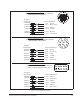
Table 7.8 - Wiring Signal and Control I/O to the Terminal Strip (Continued)
Terminal
Number Description Parameters/Wiring Connections
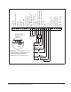
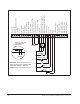
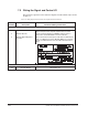
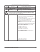
Wiring an Additional Ramp Input
18 Digital Input 7
(Default - Ramp1/Ramp2)
Digital input 7 is control function programmable through
parameter P.007. The following parameters must be set:
• P.000:Control Source
• P.001:Accel Time 1 (Ramp 1)
• P.002:Decel Time 1 (Ramp 1)
• P.006:Second Menu Password
• P.007:Terminal Strip Digital Inputs Configure (Selects and
assigns a control function to digital inputs 6 to 8)
• P.008:Terminal Strip Speed Reference Source (Analog
Motor Operated Potentiometer (MOP), or Preset Speeds)
• P.017:Accel Time 2 (Ramp 2)
• P.018:Decel Time 2 (Ramp 2)
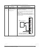
Note that based on the settings of parameters P.000, P.007,
P.008, and r.030 if an RMI board is used, the following
parameters can affect digital input 7:
• P.023:MOP Accel/Decel Time
• P.024:MOP Reset Configuration
• P.031 to P.038: Preset Speeds 1-8
Refer to the LiquiFlo Software Start-Up and Reference
manual for additional information.
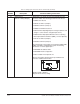
Terminal 18 On = Ramp 2
Diagram shows factory setting.