
Owner manual

7-6
LiquiFlo AC Power Modules, Hardware Reference Version 6.4
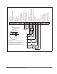
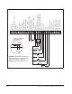
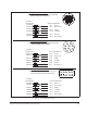
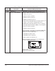
Figure 7.2 – Three-Wire Start/Stop Sample Control Wiring
12 435
19
7698
10 12
11
1413 15 1716 18 2220
21
2423 25
292726 28 30
31
5K ohm
Run
Reset
Stop
Jog
Start
Function Loss
Rev
Fwd
Remote 4-20 mA
+20 mA
+-
Speed/Torque
Reference
Important: A maintained function loss
switch should be used if P.054 (Level
Sense Start Enable) = ON and
P.026 (Function Loss Response) = 1.
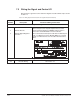
N.O. Relay Common
N.C. Relay Common
N.C. Relay Contact
+24 VDC Common
No Connection
+24 VDC Common
Start
Stop
Reset
Isolated Reference Voltage
VDC Speed Reference
mA Speed Reference
Isolated Reference Gnd
+24 VDC
Digital Input 8 (Remote/Local)
Digital Input 7 (Ramp1/Ramp2)
Digital Input 6 (Forward/Reverse)
Function Loss
Run / Jog
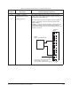
Phase A
+15 VDC
RS-232 Regulator Common
RS-232 RX
RS-232 TX
Analog Meter Output
Regulator Common
Phase B NOT
Phase B
Regulator Common
N.O. Relay Contact
Phase A NOT