
Owner manual
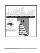
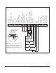
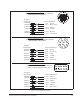

Wiring the Regulator Board and RMI Board Terminal Strips
7-5
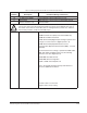
Figure 7.1 – Two-Wire Start/Stop Sample Control Wiring
2 43
5
N.O. Relay Common
Reset
Start/Stop
Jog
Run
Function Loss
19
5K ohm
Rev
Fwd
7698
10 12
11
1413
15
17
16
18
2220
21
2423 25
29
27
26
28 30
31
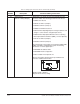
Remote 4-20 mA
1312 14 15
+20 mA
+-
Speed/Torque
Reference
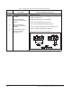
N.O. Relay Contact
N.C. Relay Common
N.C. Relay Contact
+24 VDC Common
No Connection
+24 VDC Common
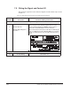
Start
Stop
Reset
Isolated Reference Voltage
VDC Speed Reference
mA Speed Reference
Isolated Reference Gnd
+24 VDC
Digital Input 8 (Remote/Local)
Digital Input 7 (Ramp1/Ramp2)
Digital Input 6 (Forward/Reverse)
Function Loss
Run / Jog
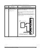
Phase A
+15 VDC
RS-232 Regulator Common
RS-232 RX
RS-232 TX
Analog Meter Output
Regulator Common
Phase B NOT
Phase B
Phase A NOT
Regulator Common
Important: A maintained function loss
switch should be used if P.054 (Level
Sense Start Enable) = ON and
P.026 (Function Loss Response) = 1.