
Owner manual

Wiring the Regulator Board and RMI Board Terminal Strips
7-3
.
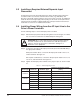
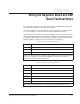
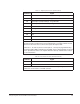
Table 7.5 – Digital Input Connections (Terminals 16-25)
Terminal # Signal
16 +24 VDC (Current Limited) (For remote control digital inputs only)
17 Digital Input 8 (Remote/Local) - Programmable
18 Digital Input 7 (Ramp1/Ramp2) - Programmable
19 Digital Input 6 (Forward/Reverse) - Programmable
20 Function Loss
21 Run/Jog
22 Reset
23 Stop
24 Start
25 +24 VDC Common
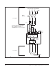
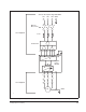
Notes: When a user-installed function loss input, a coast-to-stop pushbutton, or another
external interlock is installed, the factory-installed jumper connecting terminals 16 and
20 must be removed so that a contact, when open, will stop the drive.
Terminals 17, 18, and 19 (remote control inputs 8, 7, and 6) are programmed using
parameters P.007, P.008, and P.031 through P.038. Factory default settings are shown
here in parentheses. Refer to the LiquiFlo Software Start-Up and Reference manual
for more information.
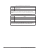
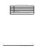
Table 7.6 – Reserved Connections (Terminals 26 and 27)
Teminal # Signal
26 No Connection
27 +24 VDC Common
Notes: Terminal 26 has no connection and is not used in LiquiFlo applications.
Terminal 27 can be used as a 24 VDC common.