
Owner manual


About the Drive
2-13
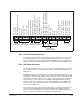
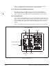
Figure 2.8 – Typical Regulator Board Terminal Strip Connections
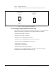
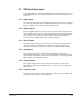
2.6.3 RS-232 Communication Port
The Regulator board contains a 9-pin D-shell RS-232 communication port (J8). This
port provides RS-232 communication between the LiquiFlo drive and a personal
computer running the Control and Configuration (CS3000) software. See
figure 2.5.
Refer to instruction manual D2-3348 for more information about the CS3000 software.
2.6.4 RMI Board Connector
The flat-ribbon cable connector (J3) on the left side of the Regulator board is a parallel
bus connection port that is used on LiquiFlo drives for the Remote Meter Interface
(RMI) board.
The RMI board provides an extended set of terminal strip inputs and outputs for the
LiquiFlo drive. When the drive control source is the terminal strip (P.000 = rE), the RMI
board can be used to provide additional speed reference selections. The RMI board
also provides an outer PI regulator that is used to adjust trim. An optional adjustable
torque (vector) or current (V/Hz) limit is available using the RMI board's analog or
frequency input. See section 2.7 for a more detailed description of the RMI board.
Refer to section 7.4 for a detailed description of the RMI terminal strip signals, and
how to wire the RMI board.
The J3 connector can also be used to provide a means of attaching optional boards
such as the DeviceNet
Option board, the AutoMax Network Option board, or
similar boards to the LiquiFlo drive. Note that you must first remove the RMI board
before a communication board can be added to the LiquiFlo drive.
12 435
19
7698
10 1211 1413 15 17
16
18 22
20
21
2423 25
292726 28 30
31
RS-232
Connections Connections
Encoder
Output
Analog
Reference
Analog Speed
Configurable
Status Relays
Digital Inputs
(Isolated 24 VDC)
Factory
Installed
N.O. Relay Common
N.O. Relay Contact
N.C. Relay Common
N.C. Relay Contact
+24 VDC Common
No Connection
+24 VDC Common
Start
Stop
Reset
Isolated Reference Voltage
VDC Speed Reference
Ma Speed Reference
Isolated Reference Gnd
+24 VDC
Digital Input 8 (Remote/Local)
Digital Input 7 (Ramp1/Ramp2)
Digital Input 6 (Forward/Reverse)
Function Loss
Run / Jog
Phase A
+15 VDC
RS-232 Regulator Common
RS-232 Rx
RS-232 Tx
Analog Meter Output
Regulator Common
Phase B Not
Phase B
Phase A Not
Regulator Common
Jumper