
Owner manual


2-12
LiquiFlo AC Power Modules, Hardware Reference Version 6.4
Step 7. Reapply input power.
Step 8. Verify that parameter P.012 is set correctly for either speed or current.
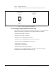
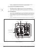
2.6.2 Wiring the Regulator Board Terminal Strip
The terminal strip on the Regulator board provides terminals for connecting customer
I/O devices. See figures 2.5 and 2.8. The following terminals are provided:
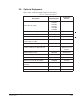
• Terminals 1-3: RS-232 connections
• Terminals 4-9: encoder connections
• Terminals 10-11: analog output connections
• Terminals 12-15: analog speed/torque reference connections
• Terminals 16-25: 24 VDC digital input connections
• Terminal 26: no connection
• Terminal 27: 24 VDC common
• Terminals 28-31: status relay connections
See chapter 7 for a complete description of, and how to wire, all of the signals
available through the Regulator board terminal strip.
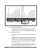
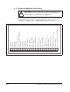
Figure 2.7 – Jumper J17 Settings for Analog Outputs
J17 J17
+10 VDC
Voltage Output Option
Pins 2-3
Current Output Option
Pins 1-2
4-20 mA
(default)