
User Manual

G-8 LiquiFlo AC Drive, Software Reference Version 6.4
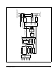
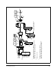
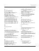
Figure G.7 – Outer Control Loop Block Diagram
OCL output
(to spd loop block diag)
*
Available in network
read registers
Ki (U.046)
+
-
Kp (U.045)
PI
Init
Rst
Netw OCL enable bit (d1, r32, b5)
or RMI digital input
OCL L/L Ratio
(U.043)
OCL fdbk
select
(U.040)
U.017
Div
(from spd loop block diag)
OCLPropTrim
Enable (U.048)
Lead/
Lag
OCL L/L Low
Freq (U.042)
OCL L/L Select
U.041)
Rst
Input
Speed PI Output (torque ref)
Scaled TS Analog Input
(4095 @ 10vdc)
Init
Running
OCL enabled
(d1, r26, b2)
*
*
*
*
OCL
feedback
*
0
0
1
ON
OFF
Mult
K
|x|
Spd ref S-curve
block output
x
U.047
100
x U.044
Lim
+/-4095
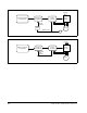
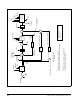
Broadcast 1
0
1
P.064
8
RMI Analog Input
0
1
P.064
P.038
8
P.031
0
1
P.064
P.038
8
P.031
P.038
Option Board
Installed
None
RMI
Network - See
network specific
I/M for details.
Broadcast 8
Direct
20 msec scan period