
User Manual

G-6 LiquiFlo AC Drive, Software Reference Version 6.4
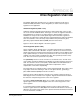
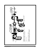
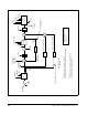
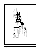
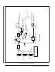
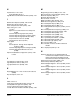
Figure G.5 – Speed Loop Detail Drawing of the Vector Regulator
Torque
Controller
Spd fdbk
S-curve
Rate
output
Current
compounding
Speed PI
Output
+
+
-
PI
Lim
Speed PI limits
+
x U.026
OCL output
+/- U.017
(from OCL
block diag)
(To Outer
Control Loop)
(To Outer Control
Loop)
-
x U.028
+
+
+
+
Inertia compensation (WR
2
)
x U.027
Network Inertia comp
Network Inertia comp
enable
Losses compensation
*
*
*
*
*
Iq Fdbk
Torque
reference
*
Iq ref limits
P.019
P.001/017
P.002/018
Ramp
Stop
0
Speed Ref
1
2
1
If AutoMax option, then drop 1, register 35
If ControlNet option, then fourth word of scheduled data
2
If AutoMax option, then drop 1, register 53, bit 1
If ControlNet option, then N10:30 bit 1
0
1
*Available in network option
read registers
U.013
U.012
KpKi
U.014
U.015
U.019
U.020
U.032