
Instruction Manual


7-4 LiquiFlo 1.5 AC Power Modules, Hardware Reference Version 1.2
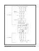
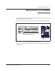
7.3 Digital Outputs
The AC Line I/O board terminal block provides terminals for six digital outputs.
However, only two digital outputs are availble on LiquiFlo 1.5 drives (terminals 27 to
32). These digital outputs can be configured for any of the 30 functions controlled by
Digital Out1 Sel (380) and Digital Out2 Sel (384).
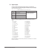
Digital Out1 Sel (380) and Digital Out2 Sel (384) can be assigned the following values:
Refer to the LiquiFlo 1.5 Software Startup and Reference (D2-3495) for more detailed
parameter descriptions.
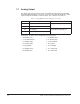
Table 7.3 – Digital Output Connections (Terminals 26 and 27)
Teminal # Signal Related Parameters
27 N.C. (Normally Closed) See Digital Out1 Sel (380) and
Digital Out2 Sel (384) below.
28 Common 5
29 N.O. (Normally Open
30 N.C. (Normally Closed)
31 Common 6
32 N.O. (Normally Open
• 1 = Fault • 15 = At PI Error
• 2 = Alarm • 16 = DC Braking
• 3 = Ready • 17 = Curr Limit
• 4 = Run • 18 = Economize
• 5 = Forward Run • 19 = Motor Overld
• 6 = Reverse Run • 20 = Power Loss
• 7 = Auto Restart • 21 = Input 1 Link
• 8 = Reserved • 22 = Input 2 Link
• 9 = At Speed • 23 = Input 3 Link
• 10 = At Freq • 24 = Input 4 Link
• 11 = At Current • 25 = Input 5 Link
• 12 = At Torque • 26 = Input 6 Link
• 13 = At Temp • 27 = Shunt Trip
• 14 = At Bus Volts • 28 = Aux Run