
Instruction Manual
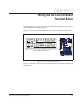


Wiring the AC Line I/O Board Terminal Block 7-3
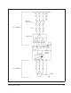
7.2 Digital Inputs
The AC Line I/O board terminal block provides terminals for four digital inputs
(terminals 22 to 26). These digital inputs can be configured for any of the 28 functions
controlled by Digital In1 Sel (361) through Digital In4 Sel (364). Note that only 4 digital
inputs can be used. See table 7.2.
.
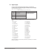
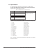
Digital In1 Sel (361) through Digital In4 Sel (364) can be assigned the following
values:
Refer to the LiquiFlo 1.5 Software Startup and Reference (D2-3495) for more detailed
parameter descriptions.
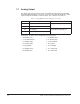
Table 7.2 – Digital Input Connections (Terminals 16-25)
Terminal # Signal Related Parameters
22 Logic Common See Digital In1 Sel (361) and
Digital In2 Sel (362) below.
23 Digital Input1
24 Digital Input2
25 Digital Input3
26 Digital Input4
• 0 = Not Used • 16 = Speed Sel 2
• 1 = Enable • 17 = Speed Sel 3
• 2 = Clear Faults • 18 = Auto/Manual
• 3 = Function Loss • 19 = Reserved
• 4 = Stop - CF • 20 = Acc2 & Dec2
• 5 = Start • 21 = Accel 2
• 6 = Fwd/Reverse • 22 = Decel 2
• 7 = Run • 23 = MOP Inc
• 8 = Run Forward • 24 = MOP Dec
• 9 = Run Reverse • 25 = OIM Control
• 10 = Jog • 26 = PI Enable
• 11 = Jog Forward • 27 = PI Hold
• 12 = Jog Reverse • 28 = PI Reset
• 13 = Stop Mode B • 29 = Pwr Loss Lvl
• 14 = Bus Reg Md B • 30 = Precharge En
• 15 = Speed Sel 1 • 31 = Reserved