
Instruction Manual
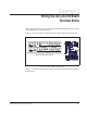


7-2 LiquiFlo 1.5 AC Power Modules, Hardware Reference Version 1.2
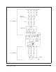
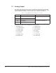
7.1 Analog Output
The single analog output channel can be configured using Analog Out Config (340)
and Analog Out1 Sel (342) to select any one of 13 analog outputs. Terminals 1 and 2
output 4 to 20 mA. Terminals 17 and 18 output -10 to +10 volts. See table 7.1
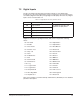
Analog Out1 Sel (342) can be assigned the following values:
Table 7.1 – Analog Output Connection (Terminals 1- 2 or 17-18)
Terminal # Signal Related Parameters
1 I1- (Current -) Analog Out Config (340) =1
2 I1+ (Current +)
17 V1- (Voltage -) Analog Out Config (340) = 0
18 V1+ (Voltage +)
• 0 = Output Freq • 7 = DC Bus Volts
• 1 = Command Freq • 8 = PI Reference
• 2 = Output Amps • 9 = PI Feedback
• 3 = Torque Amps • 10 = PI Error
• 4 = Flux Amps • 11 = PI Output
• 5 = Output Power • 12 = %Motor OL
• 6 = Output Volts • 13 = %Drive OL