Hardware Reference, Installation, and Troubleshooting Manual D2-3494-2 LiquiFlo 1.5 AC Power Modules Version 1.
Important User Information Solid-state equipment has operational characteristics differing from those of electromechanical equipment. Safety Guidelines for the Application, Installation and Maintenance of Solid State Controls (publication SGI-1.1 available from your local Rockwell Automation sales office or online at http://www.rockwellautomation.com/literature/) describes some important differences between solid-state equipment and hard-wired electromechanical devices.
CONTENTS Chapter 1 Introduction 1.1 Related Publications ........................................................................................ 1-1 1.2 Getting Assistance from Reliance Electric....................................................... 1-1 Chapter 2 About the Drive 2.1 Identifying the Drive by Model Number ........................................................... 2-1 2.2 Enclosure Ratings ........................................................................................... 2-2 2.
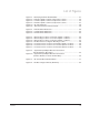
Chapter 5 Installing Input Power Wiring 5.1 Installing Transformers and Reactors (Optional) .............................................5-1 5.2 Installing Fuses for Branch Circuit Protection ..................................................5-1 5.3 Installing a Required External/Separate Input Disconnect...............................5-4 5.4 Installing Power Wiring from the AC Input Line to the Drive’s Power Terminals ........................................................................................
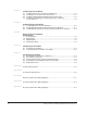
List of Figures Figure 2.1 – Identifying the Drive Model Number ..................................................... 2-1 Figure 2.2 – B-Frame LiquiFlo 1.5 Drive Component Locations............................... 2-3 Figure 2.3 – C-Frame LiquiFlo 1.5 Drive Component Locations .............................. 2-5 Figure 2.4 – D-Frame LiquiFlo 1.5 Drive Component Locations .............................. 2-7 Figure 2.5 – AC Line I/O Board ..........................................................................
IV Trane LiquiFlo 2.
List of Tables Table 2.1 – Power and Enclosure Ratings ............................................................... 2-2 Table 2.2 – Available Kits and Options................................................................... 2-10 Table 3.1 – Environmental Conditions...................................................................... 3-2 Table 3.2 – Drive Dimensions and Weights.............................................................. 3-2 Table 3.3 – Recommended Power Wire Sizes for B-Frame Drives.
VI Trane LiquiFlo 2.
CHAPTER 1 Introduction This instruction manual describes the LiquiFlo¥ 1.5 drive’s Power Module and regulator hardware. It does not cover the LiquiFlo software. For software information, refer to the LiquiFlo 1.5 AC General Purpose (V/Hz) and Vector Duty Drive Software Start-Up and Reference Manual (D2-3495). This manual is intended for qualified electrical and plumbing personnel. LiquiFlo drives will typically be referenced by frame size.
1-2 LiquiFlo 1.5 AC Power Modules, Hardware Reference Version 1.
CHAPTER 2 About the Drive This chapter describes how to identify the drive using the model number matrix and shows the major drive components. The LiquiFlo 1.5 AC drive is a PWM (pulse-width-modulated) liquid-cooled drive that provides vector and general purpose regulation for a wide range of applications. 2.1 Identifying the Drive by Model Number Each LiquiFlo 1.5 AC drive can be identified by its model number. See figure 2.1. This number appears on the shipping label and on the drive’s nameplate.
Table 2.
1 2 14 13 3 12 4 11 5 6 10 7 9 8 Front View Figure 2.2 – B-Frame LiquiFlo 1.
2.4 C-Frame LiquiFlo 1.5 Drive Component Locations The C-Frame LiquiFlo 1.5 drives have the following main components. The numbered items listed below provided correspond to the numbers used in figure 2.3. Replacement parts are listed in chapter 9. 1. 2. 3. 4. 5. 6. 7. 8. 9. 10. 11. 12. 13. 14. 15.
1 2 3 4 15 5 6 14 13 7 12 8 9 11 10 Front View Figure 2.3 – C-Frame LiquiFlo 1.
2.5 D-Frame LiquiFlo 1.5 Drive Component Locations The D-Frame LiquiFlo 1.5 drives have the following main components. The numbered items listed below provided correspond to the numbers used in figure 2.4. Replacement parts are listed in chapter 9. 1. 2. 3. 4. 5. 6. 7. 8. 9. 10. 11. 12. 13.
1 2 3 4 5 6 13 7 8 9 10 11 12 Front View Figure 2.4 – D-Frame LiquiFlo 1.
2.6 AC Line I/O Board Description The following signals are available at the AC Line I/O board terminal block. Refer to figure 2.5 for terminal identification. 2.6.1 Digital Inputs The AC Line I/O board terminal block provides terminals for four digital inputs (terminals 22 to 26). These digital inputs can be configured for any of the 28 functions controlled by Digital In1 Sel (361) through Digital In6 Sel (366). Note that only 4 digital inputs can be used. 2.6.
2.7 DPI Communication Port The DPI Communication Interface board contains a DIN connector that is used as a DPI communication port. This port provides communication between the LiquiFlo 1.5 drive and another DPI device (for example, an OIM or a personal computer running the VS Utilities software). See figure 2.6. Refer to instruction manual D2-3488 for more information about the VS Utilities software. DPI Port 3 Figure 2.
2.8 Optional Equipment Table 2.2 lists standard LiquiFlo 1.5 kits and options. Table 2.2 – Available Kits and Options Model Number Instruction Manual Operator Interface Module (OIM) RE1LCDH D2-3495 OIM LCD external-mount harness RECBL-LCD n/a RECOMM-232 D2-3488 Description Serial Converter with VS Utilities Software 2-10 LiquiFlo 1.5 AC Power Modules, Hardware Reference Version 1.
CHAPTER 3 Planning the Installation This chapter provides how to plan a LiquiFlo 1.5 drive installation. ! ATTENTION: Only qualified electrical personnel familiar with the construction and operation of this equipment and the hazards involved should install, adjust, operate, or service this equipment. Read and understand this manual and other applicable manuals in their entirety before proceeding. Failure to observe this precaution could result in severe bodily injury or loss of life.
Table 3.1 – Environmental Conditions 1 Condition Specification Operating Temperature (inside a NEMA cabinet) 0qC to 55qC1 32q to 131qF Storage Temperature (Ambient) -40qC to 65qC 40q to 149qF Humidity 5% to 95% (non-condensing) With typical heat rise inside a cabinet, 40qC ambient outside usually results in 55qC inside. 3.1.2 Determining Total Area Required Based on Drive Dimensions Drive dimensions and weights are listed in table 3.2. Overall drive dimensions are illustrated in figures 3.
A D C F B E 0.56 4 Places G Front View Right Side View Figure 3.
A C D 1.09 B E 1.00 .562 4 Places Front View (Control Panel Assembly Removed) Right Side View Figure 3.2 – C-Frame Drive Dimensions 3-4 LiquiFlo 1.5 AC Power Modules, Hardware Reference Version 1.
A C F 13.93 D 16.50 0.562 6 Places B E Left Side View G Front View Figure 3.
3.1.3 Verifying the Site Provides for Recommended Air Flow Clearances Be sure there is adequate clearance for air circulation around the user-supplied enclosure. A 6-inch minimum clearance is required wherever vents are located in the cabinet. 3.1.4 Verifying Power Module Input Ratings Match Supplied Power It is important to verify that plant power will meet the input power requirements of the LiquiFlo drive’s Power Module circuitry. Refer to table 2.1 for input power rating specifications.
Table 3.3 – Recommended Power Wire Sizes for B-Frame Drives Type of Power Wiring Drive M/N LF150414R4, LF150414W4 with kit M/N LF150414W4PM AC Input Power (R/L1, S/L2, T/L3) Output Power (U/T1, V/T2, W/T3) Delta-Wye Transformer (S1 to S6) Use lugs1 that will accept two (2) 300 MCM to 6 AWG conductors Ground (PE) 1 Lugs not provided with standard drive. They are available as part of kit M/N LF150414W4PM. Table 3.
3.2.1.4 Recommended Motor Lead Lengths Motor lead lengths can total up to 76 meters (250 feet). 3.2.2 Selecting Input Line Branch Circuit Fuses ! ATTENTION: Most codes require that upstream branch circuit protection be provided to protect input power wiring. Install the fuses recommended in table 3.6. Do not exceed the fuse ratings. Failure to observe this precaution could result in damage to, or destruction of, the equipment.
CHAPTER 4 Mounting the Drive, Grounding, and Finding Wire Routing Locations This chapter shows how to mount the drive and properly ground it. Also shown are the entry areas where wiring is to be routed in and out of the drive. 4.1 Lifting and Mounting the Drive Use the following procedure to lift the LiquiFlo 1.5 drive and mount it in the required enclosure: Step 1. For M/N LF150500R4, LF150500W4, LF150643R4, or LF150643W4, install two eyebolts into the drive to serve as lifting points.
In order to maintain a flat mounting surface and to ensure that bolt tightness is maintained, use flat washers and split-ring lock washers under the bolt heads. Refer to table 3.2 and figures 3.1 to 3.3 for drive mounting dimensions. Use the following user-supplied mounting bolts and washers on C-frame drives: 1/2”-13, UN/UNC-2A, Grade 2. Step 7. For M/N LF150500R4, LF150500W4, LF150643R4, or LF150643W4, remove the eyebolts and the chain between them.
Drive Input Wiring (6 Places) Drive Output Wiring (3 Places) Coolant Connections Top View User WiringConnection User Connections Front View Bottom View Figure 4.1 – Wire Routing Locations for B-Frame LiquiFlo 1.
Drive Input Wiring (6 Places) Drive Output Wiring To Motor (3 Places) User Connections Coolant Connections Left Side View Front View Figure 4.2 – Wire Routing Locations for C-Frame LiquiFlo 1.5 Drives 4-4 LiquiFlo 1.5 AC Power Modules, Hardware Reference Version 1.
Drive Input Wiring (6 Places) L1 U L2 L3 V L4 Drive Output To Motor (3 Places) L5 W L6 Left Side View User Control Connections Front View User Control Wire Openings Bottom View Figure 4.3 – Wire Routing Locations for D-Frame LiquiFlo 1.
4.3 Installing the DC Bus Reactor Fan (C-Frame Drives Only) A fan must be installed in the LiquiFlo 1.5 drive enclosure to keep the DC bus reactor at the proper operating temperature. The fan should be a Comair Rotron M/N PT2B3 rated at 0.26 amps, 31 watts, 235 CFM (115 VAC, 60 Hz), or equivalent. Use the following procedure to install the DC bus reactor fan: Step 1. Open the door of the enclosure. Step 2. Mount the fan beneath the drive in the enclosure as shown in figure 4.
4.4 Grounding the Drive ! ATTENTION: The user is responsible for conforming with all applicable local, national, and international codes. Failure to observe this precaution could result in damage to, or destruction of, the equipment. Use the following steps to ground the drive: Step 1. Open the door of the enclosure. Step 2. Run a suitable equipment grounding conductor unbroken from the drive to the motor’s ground terminal and then to earth ground.
pump not be powered unless the drive is also powered. Failure to do this may result in condensation accumulating on the casting and/or circuit boards, which could damage the drive. 4.5.3 D-Frame Coolant Connections D-frame LiquiFlo 1.5 drives have inlet and outlet coolant connections as shown in figure 4.7. The inlet and outlet connections are tapped holes suitable for two bolt-hole flanges. The internal threads of the tapped holes are 5/16-18 UNC-2B. The depth of thread is 3/4".
Coolant Outlet Connection Coolant Inlet Connection Bottom View Figure 4.6 – Coolant Connector Locations for C-Frame LiquiFlo 1.5 Drives Coolant Inlet Connection Front View Coolant Outlet Connection Figure 4.7 – Coolant Connector Locations for D-Frame LiquiFlo 1.
4-10 LiquiFlo 1.5 AC Power Modules, Hardware Reference Version 1.
CHAPTER 5 Installing Input Power Wiring This chapter describes incoming line components and how to install them. 5.1 Installing Transformers and Reactors (Optional) The LiquiFlo 1.5 AC drive may be used on distribution systems with 85,000 amps or less symmetrical fault current capacity. Line reactors are not needed for safe operation of the drive but may be required to reduce line harmonics.
3-Phase AC Input Voltage 380/480 V L2 L1 L3 GND Manual Disconnect User-Supplied Fuse GND (PE) L1 L2 L3 L6 L5 L4 LiquiFlo 1.5 Power Module U V W User-Supplied M GND Figure 5.1 – Typical AC Input/Output Electrical Connections (6-Pulse Rectifier, All Frames) 5-2 LiquiFlo 1.5 AC Power Modules, Hardware Reference Version 1.
3-Phase AC Input Voltage 380/480 V 181 182 183 GND Manual Disconnect User-Supplied Fuse Transformer L1 L2 L3 L6 L5 L4 GND (PE) LiquiFlo 1.5 Power Module U V W User-Supplied M GND Figure 5.
5.3 Installing a Required External/Separate Input Disconnect An input disconnect must be installed in the line before the drive input terminals in accordance with local, national, and international codes (e.g., NEC/CEC). The disconnect should be sized according to the in-rush current as well as any additional loads the disconnect might supply. The trip rating for the inrush current (10-12 times full load current) should be coordinated with that of the input isolation transformer, if used.
CHAPTER 6 Installing Output Power Wiring This chapter provides instructions on wiring output contactors, motor overload protection, and output wiring to the motor. 6.1 Installing Output Contactors (Optional) Output contactors provide a positive means of disconnecting the motor from the drive. If the application requires the use of output contactors, contact Reliance Electric for assistance. 6.
6.3 Installing Output Wiring from the Drive Output Terminals to the Motor Important: The total motor lead length must not exceed 76 meters (250 feet). Use the following steps to connect the AC output power wiring from the drive to the motor: Step 1. Wire the three-phase AC output power motor leads by routing them as shown in figures 4.1, 4.2, or 4.3. Tables 3.3, 3.4, and 3.5 contain the recommended power wiring sizes. Do not route more than three sets of motor leads through a single conduit.
CHAPTER 7 Wiring the AC Line I/O Board Terminal Block This chapter describes how to wire the AC Line I/O board terminal block for the analog output, digital inputs, and digital outputs. Figure 7.1 shows the terminal assignments for the AC Line I/O board terminal block. AC Line I/O Terminal Block AC Line I/O Board Figure 7.1 – AC LIne I/O Board Terminal Block Sections 7.1 through 7.3 describe the signals available through the AC Line I/O board terminal block.
7.1 Analog Output The single analog output channel can be configured using Analog Out Config (340) and Analog Out1 Sel (342) to select any one of 13 analog outputs. Terminals 1 and 2 output 4 to 20 mA. Terminals 17 and 18 output -10 to +10 volts. See table 7.1 Table 7.
7.2 Digital Inputs The AC Line I/O board terminal block provides terminals for four digital inputs (terminals 22 to 26). These digital inputs can be configured for any of the 28 functions controlled by Digital In1 Sel (361) through Digital In4 Sel (364). Note that only 4 digital inputs can be used. See table 7.2. . Table 7.
7.3 Digital Outputs The AC Line I/O board terminal block provides terminals for six digital outputs. However, only two digital outputs are availble on LiquiFlo 1.5 drives (terminals 27 to 32). These digital outputs can be configured for any of the 30 functions controlled by Digital Out1 Sel (380) and Digital Out2 Sel (384). Table 7.3 – Digital Output Connections (Terminals 26 and 27) Teminal # Signal 27 N.C. (Normally Closed) 28 Common 5 29 N.O. (Normally Open 30 N.C.
7.4 Stopping the Drive ! ATTENTION: The user must provide an external, hardwired emergency stop circuit outside of the drive circuitry. This circuit must disable the system in case of improper operation. Uncontrolled machine operation may result if this procedure is not followed. Failure to observe this precaution could result in bodily injury.
7-6 LiquiFlo 1.5 AC Power Modules, Hardware Reference Version 1.
CHAPTER 8 Completing the Installation This chapter provides instructions on how to perform a final check of the installation before power is applied to the drive. ! 8.1 ATTENTION: Only qualified electrical personnel familiar with the construction and operation of this equipment and the hazards involved should start and adjust it. Read and understand this manual in its entirety before proceeding. Failure to observe this precaution could result in severe bodily injury or loss of life.
Step 10. Check the motor installation and length of motor leads. Step 11. Disconnect any power correction capacitors connected between the drive and the motor. Step 12. Check that the rating of the transformer (if used) matches the drive requirements and is connected properly. Step 13. Verify that a properly-sized ground wire is installed and a suitable earth ground is used. Check for and eliminate any grounds between the motor frame and the motor power leads. Verify that all ground leads are unbroken.
CHAPTER 9 Troubleshooting the Drive This chapter describes how to troubleshoot the drive and the equipment that is needed to do so. Also provided are replacement part lists and information on clearing faults. 9.1 Test Equipment Needed To Troubleshoot An isolated multimeter will be needed to measure DC bus voltage and to make resistance checks. Note that dedicated troubleshooting test points are not provided. 9.
Step 3. Measure the DC bus potential with a voltmeter while standing on a non-conductive surface and wearing insulated gloves (1000 V). Measure the DC bus potential at the test points on the Power Interface Control (PIC) board (see figure 9.1). For additional wiring information, refer to Appendix C, Appendix D, or Appendix E. Step 4. Once the drive has been serviced, reapply input power. Initial DC Bus Measurement Points POS (+) NEG (-) Power Interface Control Board Figure 9.
9.4 Checking the Power Modules with Input Power Off Use the following procedure to check the drive’s Power Module circuitry with power off: ! ATTENTION: DC bus capacitors retain hazardous voltages after input power has been disconnected. After disconnecting input power, wait five (5) minutes for the DC bus capacitors to discharge and then check the voltage with a voltmeter to ensure the DC bus capacitors are discharged before touching any internal components.
Table 9.1 - Resistance Checks (Continued) IGBT No. Meter Connection (+) (-) 1 * W/T3 2 * V/T2 3 * U/T1 4 W/T3 ** 5 V/T2 ** 6 U/T1 ** Component is OK if resistance (R) is: 10 < R < 1 megohm Component is defective if: Continuity (short circuit) or open when the meter is connected with reversed polarity. * (+) DC Bus Volts power terminal ** (-) DC Bus Volts power terminal 9-4 LiquiFlo 1.5 AC Power Modules, Hardware Reference Version 1.
9.5 Replacement Parts Tables 9.2, 9.3, and 9.4 list the replacement parts that are available from Reliance Electric. See figures 2.2, 2.3, and 2.4 for the location of the parts. Table 9.2 – B-Frame LiquiFlo 1.
Table 9.3 – C-Frame LiquiFlo 1.
Table 9.4 – D-Frame LiquiFlo 1.
9-8 LiquiFlo 1.5 AC Power Modules, Hardware Reference Version 1.
APPENDIX A Technical Specifications Table A.1 – Service Conditions AC Line Distribution System Capacity (maximum) for 460 VAC Units 85,000 amps symmetrical fault current capacity. Short circuit rating may be limited to 65,000 amps if a circuit breaker is used instead of fuses. Control Method All-digital vector, sinusoidal pulse-width-modulated (PWM) Displacement Power Factor 0.
Table A.2 – Environmental Conditions Condition Specification Operating Temperature (inside an enclosure) 0qC to 55qC* 32qF to 131qF Storage Temperature (Ambient) -40qC to 65qC 40qF to 149qF Humidity 5% to 95% (non-condensing) *User-supplied cabinet air cooling system must provide adequate heat dissipation to maintain an internal temperature not to exceed 55qC. Refer to table 2.1 for drive air watts loss.
APPENDIX B Cooling System Specifications LF150414W4 LF150414R4 LF150500W4 LF150643W4 LF150500R4 LF150643R4 LF151200W4 LF151200R4 Coolant Type Potable water Refrigerant with no additives. Potable water Refrigerant with no additives. Potable water with approved corrosion inhibitor1. Inlet Coolant Temperature Range See note3. 15oC to 40oC o o 2 (60 F to 104 F) See note3. 15oC to 40oC o o 2 (60 F to 104 F) 15oC to 40oC See note3. o o 2 (60 F to 104 F) See note3. 5.0 gpm See note3. 8.
B-2 LiquiFlo 1.5 AC Power Modules, Hardware Reference Version 1.
APPENDIX C B-Frame LiquiFlo Drive Wiring Diagrams Replace with file C.fm (17 x 11, z-fold).
C-2 LiquiFlo 1.5 AC Power Modules, Hardware Reference Version 1.
APPENDIX D C-Frame LiquiFlo Drive Wiring Diagrams Replace with file D.fm (17 x 11, z-fold).
D-2 LiquiFlo 1.5 AC Power Modules, Hardware Reference Version 1.
APPENDIX E D-Frame LiquiFlo Drive Wiring Diagrams Replace with file E.fm (17 x 11, z-fold).
E-2 LiquiFlo 1.5 AC Power Modules, Hardware Reference Version 1.
INDEX A E AC line distribution system capacity, A-1 AC Line I/O board description, 2-8 wiring, 7-1 to 7-4 Air flow, 3-6 Alarms, drive, 9-1 Analog output, 2-8 Emergency stop, wiring, 7-5 Enclosure ratings, 2-2 Environmental conditions, 3-1 B F Faults, drive, 9-1 Fuses, input line branch circuit, 3-8 G Branch circuit fuses, installing, 5-1 to 5-3 Grounding, 4-7 C Carrier frequency, A-1 Checking the installation, 8-1 Clearance, air flow, 3-6 Component locations B-frame, 2-2 to 2-3 C-frame, 2-4 to 2-5 D
P Stopping the drive, 7-5 Power and enclosure ratings, 2-2 Power loss watts rating, 2-2 Power wire sizes, 3-7 Power wiring, installing, 5-4 T Replacement parts, 9-5 Technical assistance, 1-1 Temperature operating, A-2 storage, A-2 Terminal bock, I/O, 2-8 Transformers and reactors, installing, 5-1 S W Signal wire sizes, 3-7 Site environmental conditions, 3-1 requirements for, 3-1 Stopping, 7-5 Wire routing, 4-2 to 4-5 Wire sizes control and signal, 3-7 power, 3-7 Wiring requirements, drive, 3-6 R
U.S. Allen-Bradley Drives Technical Support - Tel: (1) 262.512.8176, Fax: (1) 262.512.2222, Email: support@drives.ra.rockwell.com, Online: www.ab.com/support/abdrives www.rockwellautomation.com Power, Control and Information Solutions Headquarters Americas: Rockwell Automation, 1201 South Second Street, Milwaukee, WI 53204-2496 USA, Tel: (1) 414.382.2000, Fax: (1) 414.382.