
User Manual


67Publication LDL-UM001A-EN-P- March 2009 67
Appendix
B
Interconnect Diagrams
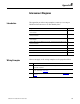
Introduction
This appendix provides wring examples to assist you in wring an
LDL-Series linear motors to an Allen-Bradley drive.
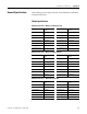
Wiring Examples
These notes apply to the wiring examples on the pages that follow.
Topic Page
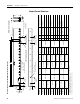
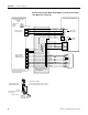
Kinetix 6000 or Kinetix 2000 Drives and LDL-xxxxxxx-xHT11 Linear Motor with
a TTL Encoder
68
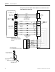
Kinetix 6000 or Kinetix 2000 Drives and LDL-xxxxxxx-xHT11 Linear Motor with
a Sin/Cos Encoder
69
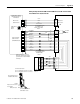
Kinetix 6000 or Kinetix 2000 Drives and LDL-xxxxxxx-xHT20 Linear Motor with
a TTL Encoder
70
Kinetix 6000 or Kinetix 2000 Drives and LDL-xxxxxxx-xHT20 Linear Motor with
a Sin/Cos Encoder
71
Ultra3000 Drives and LDL-xxxxxxx-xHT11 Linear Motor with a TTL Encoder 72
Ultra3000 Drives and LDL-xxxxxxx-xHT11 Linear Motor with a Sin/Cos Encoder 73
Ultra3000 Drives and LDL-xxxxxxx-xHT20 Linear Motor with a TTL Encoder 73
Ultra3000 Drives and LDL-xxxxxxx-xHT20 Linear Motor with a Sin/Cos Encoder 75
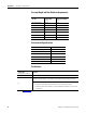
Note Information
1
Use cable shield clamp in order to meet CE requirements. No external connection
to ground is required.
2
For motor cable specifications, refer to the Kinetix Motion Control Selection
Guide, publication GMC-SG001.
3
When using Sin/Cos encoder with Kinetix 6000 drives refer to Appendix C on
page 77
.