
User Manual


64 Publication LDL-UM001A-EN-P- March 2009
Appendix A Specifications and Dimensions
Motor Coil Dimensions
28.00
(1.102)
80.00
(3.150)
A
B
C
D
E
F
32.00
(1.260)
1000 mm (39.37 in.)
1000 mm (39.37 in.)
1000 mm (39.37 in.)
22.00
(0.866)
M4 x 0.7
8.5 (0.33),
quantity A1.
35.00
(1.378)
26.00
(1.024)
4.50
(0.177)
38.00
(1.496)
60.00
(2.362)
0.83±0.30
(0.033±.011)
0.260 (0.010)
J
I
T
H
L
Mounting holes
Mounting holes
typical both sides,
quantity A2.
M4 x 0.7
7 (0.28)
Typical
G
28.00
(1.102)
80.00
(3.150)
350
(13.9)
600
(24)
4.50
(0.177)
35.00
(1.378)
26.00
(1.024)
A
B
C
D
E
F
L
M4 x 0.7
8.5 (0.33),
quantity A1.
Mounting holes
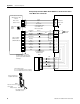
Power Cable
Flying Leads
Thermistor Cable
Flying Leads
Hall Effect Module
Flying Leads
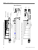
Coil Face Runout (T.I.R.)
Magnet channel
shown for reference.
Air Gap
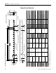
Refer to table on page 65 for coil mounting surface flatness requirement.
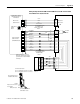
Dimensions are in mm (in.)
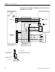
LDL-Series Ironless Linear Motor Coil Dimension (LDL-xxxxxxx-xHT20) with Flying Leads
LDL-Series Ironless Linear Motor Coil Dimension (LDL-xxxxxxx-xHT11) with Connectors
Dimensions for side view of linear motor coil with connectors is identical to this view with flying leads.
Feedback
Connector
Power
Connector
Encoder
Connector