
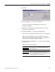
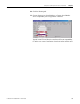
User Manual


Publication LDL-UM001A-EN-P - March 2009 59
Specifications and Dimensions Appendix A
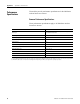
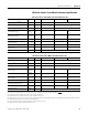
LDL-Series Ironless Linear Motor (Thick 50 mm frame size)
Attribute Units Symbol
LDL-T050120-DxTxx LDL-T050240-DxTxx LDL-T050240-ExTxx
Force, continuous
(1)
(2)
(3)
(4)
N (lbf)
F
c
110 (25) 220 (49)
Force, peak
(5)
N (lbf)
F
p
364 (82) 728 (164)
Thermal resistance °C/W
R
th
1.19 0.60
Force constant
(6)
(7)
(8)
N/A
pk
(lbf/A
pk
)
K
f
40.2
(9.0)
40.2
(9.0)
80.4
(18.1)
Back EMF constant p-p
(6)
(7)
(8)
V
p
/m/s
(V
p
/in/s)
K
e
47.4
(1.2)
47.4
(1.2)
94.9
(2.4)
Current, peak
(5)
(7)
A
pk
(A
rms
)I
p
9.1 (6.4) 18.1 (12.8) 9.1 (6.4)
Current, continuous
(1)
(2)
(3)
(4)
A
pk
(A
rms
)I
c
2.7 (1.9) 5.5 (3.9) 2.7 (1.9)
Resistance p-p @ 20 °C (68 °F)
(6)
(8)
Ohms
R
20
9.42 4.71 18.83
Inductance p-p
(6)
(8)
mH L 18 9 35.31
Magnetic attraction N (lbf)
F
a
0 (0)
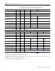
Attribute Units Symbol
LDL-T050360-DxTxx LDL-T050360-ExTxx LDL-T050480-DxTxx LDL-T050480-ExTxx
Force, continuous
(1)
(2)
(3)
(4)
N (lbf)
F
c
329 (74) 439 (99)
Force, peak
(5)
N (lbf)
F
p
1093 (246) 1457 (327)
Thermal resistance °C/W
R
th
0.40 0.30
Force constant
(6)
(7)
(8)
N/A
pk
(lbf/A
pk
)
K
f
40.2
(9.0)
120.5
(27.1)
40.2
(9.0)
80.4
(18.1)
Back EMF constant p-p
(6)
(7)
(8)
V
p
/m/s
(V
p
/in/s)
K
e
47.4
(1.2)
142.3
(3.6)
47.4
(1.2)
94.9
(2.4)
Current, peak
(5)
(7)
A
pk
(A
rms
)I
p
27.2 (19.2) 9.1 (6.4) 36.3 (25.6) 18.1 (12.8)
Current, continuous
(1)
(2)
(3)
(4)
A
pk
(A
rms
)I
c
8.2 (5.8) 2.7 (1.9) 10.9 (7.7) 5.5 (3.9)
Resistance p-p @ 20 °C (68 °F)
(6)
(8)
Ohms
R
20
3.14 28.25 2.35 9.42
Inductance p-p
(6)
(8)
mH L 5.88 52.96 4.41 17.65
Magnetic attraction N (lbf)
F
a
0 (0)
(1) Coils at maximum temperature, 130 °C (266 °F), mounted to an aluminium heat sink whose area is noted in table on page 62, and at 40 °C (104 °F) ambient.
(2) Continuous force and current based on coil moving with all phases sharing the same load in sinusoidal commutation.
(3) For standstill conditions, multiply continuous force and continuous current by 0.9.
(4) Coil mountings on either of the two narrow sides reduces continuous force by 10%.
(5) Calculated at 11% duty cycle for 1.0 second max. Some applications may produce significantly higher peak forces. Call Applications Engineering (631.344.6600) for details.
(6) Winding parameters listed are measured line-to-line (phase-to-phase).
(7) Currents and voltages listed are measured 0-peak of the sine wave unless noted as rms.
(8) Specifications are ±10%. Phase-to-phase inductance is ±30%.