
User Manual


Publication LDL-UM001A-EN-P - March 2009 37
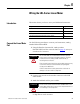
Wiring the LDL-Series Linear Motor Chapter 5
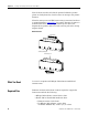
Cables Exit on Opposite Ends
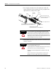
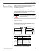
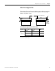
If mounting coils in tandem, such that the power cables exit opposite
to each other, as shown, use the following table to find mounting
distance and phase wiring.
Coil #1 is the master
Coil #1
Coil #2
Hall Effect
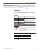
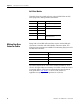
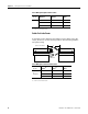
Phase Wiring for Opposite End Exit Power Cables
L1
mm (in.)
Coil # 1
Master
(1)
Coil # 2
Slave
(2)
Amplifier
Phase
90 (3.54)
or
150 (5.91)
Red Red U
White Black V
Black White W
(1) Master has Hall effect module.
(2) Slave has no Hall effect module.