
User Manual


34 Publication LDL-UM001A-EN-P - March 2009
Chapter 5 Wiring the LDL-Series Linear Motor
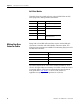
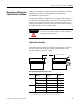
Hall Effect Module
This table shows the signal and wire colors for Hall effect module
with flying leads, catalog number LDL-HALL-F.
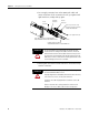
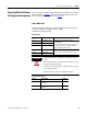
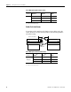
Making Your Own
Extension Cables
Flying lead coil and Hall effect modules require circular DIN style
connectors to interface with Allen-Bradley extension cables. The
following connectors kits are available for terminating flying lead coils
and Hall effect modules.
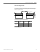
The cable length from the coil to drive should be limited to 10 m
(32.8 ft). If longer cables are necessary a 1321-3Rx-x series line reactor
is required. Refer to 1321 Power Conditioning Products Technical
Data, publication 1321-TD001
, to choose a line reactor for
applications requiring cable longer than 10 m (32.8 ft).
Color Signal Signal Spec
Red +V 5…24V DC Hall supply, 20 mA.
Black VRTN Hall effect signal common.
White S1
–
Blue S2
Orange S3
Silver braid Cable shield Terminate at drive end per drive
manual instructions.
Connector Kit Cat. No. Application
2090-KFBM4-CAAA Feedback flex extension cable
2090-KPBM4-12AA Power flex extension cable
2090-KFBE7-CAAA Feedback non-flex extension cable
2090-KPBE7-12AA Power non-flex extension cable