
User Manual

Publication LDL-UM001A-EN-P - March 2009 33
Wiring the LDL-Series Linear Motor Chapter 5
Signal and Wire Definitions
for Flying Lead Components
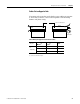
For linear motors, catalog numbers LDL-xxxxxxx-xHT20, wire using
wiring diagram on page 70
. Wire colors and signal types are shown
here, for wire gauge information see page 65
.
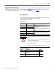
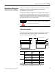
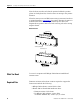
Linear Motor Coil
The following shows the wire color and signals for the linear motor
coil power and PTC thermistor cables, catalog
number LDL-xxxxxxx-xxT20.
Power Signals
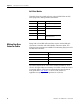
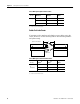
PTC Thermistor Signals
Color Signal Comments
Red Motor Phase U (A) • Observe maximum applied voltage
specification.
• Consult drive manual or supplier for specific
wiring instructions to the drive. Wiring is
phase/commutation sensitive.
White Motor Phase V (B)
Black Motor Phase W (C)
Green Motor Ground • Terminate per drive manual instructions.
• Shield is not connected to the motor frame.
Shield Cable Shield
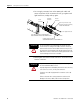
ATTENTION
Disconnect input power supply before installing or servicing
motor.
Motor lead connections can short and cause damage or injury if
not well secured and insulated.
Insulate the connections, equal to or better than the insulation
on the supply conductors.
Properly ground the motor per selected drive manual.
Color Description Signal
Black Positive Temperature Coefficient (PTC)
thermistor +
TS+
Black Positive Temperature Coefficient (PTC)
thermistor -
TS-