
User Manual

28 Publication LDL-UM001A-EN-P - March 2009
Chapter 4 LDL-Series Linear Motor Connector Data
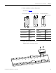
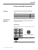
PTC Thermistor Connector
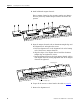
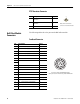
Hall Effect Module
Connectors
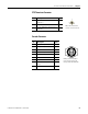
The following tables show the pinouts the Hall effect module.
Feedback Connector
Pin Description Signal
1 Positive Temperature Coefficient (PTC)
thermistor +
TS+
3 Positive Temperature Coefficient (PTC)
thermistor -
TS-
4– Reserved
1
4
3
Pin Description Signal
1 A Quad B TTL (1 V p-p), + A Differential AM+ (SIN+)
2 A Quad B TTL (1 V p-p), - A Differential AM- (SIN-)
3 A Quad B TTL (1 V p-p), + B Differential BM+ (COS+)
4 A Quad B TTL (1 V p-p), - B Differential BM- (COS+)
5 TTL + Index Mark Differential IM+
6 TTL - Index Mark Differential IM-
7 Reserved –
8
9 Encoder and Hall Sensor Power +5V DC
10 Common Common
11 Reserved –
12 Common Common
13
PTC Thermistor PTC Temp+
14 PTC Thermistor PTC Temp-
15 TTL - Trapezoidal Hall Commutation S1
16 TTL - Trapezoidal Hall Commutation S2
17 TTL - Trapezoidal Hall Commutation S3
Case Shield –
Mates with PTC thermistor
connector on Hall effect module.
1
2
3
4
5
6
7
8
9
10
11
12
13
14
15
16
17
Intercontec P/N AKUA015NN00400220000
Mating Connector Kit Allen-Bradley 2090-KFBM4-CAAA