LDL-Series Ironless Linear Servo Motors Catalog Numbers LDL-N030xxx-xHT11, LDL-N050xxx-xHT11, LDL-N075xxx-xHT11, LDL-T030xxx-xHT11, LDL-T050xxx-xHT11, LDL-T075xxx-xHT11, LDL-N030xxx-xHT20, LDL-N050xxx-xHT20, LDL-N075xxx-xHT20, LDL-T030xxx-xHT20, LDL-T050xxx-xHT20, LDL-T075xxx-xHT20, LDL-N030xxx, LDL-N050xxx, LDL-N075xxx, LDL-T030xxx, LDL-T050xxx, LDL-T075xxx User Manual
Important User Information Solid state equipment has operational characteristics differing from those of electromechanical equipment. Safety Guidelines for the Application, Installation and Maintenance of Solid State Controls (publication SGI-1.1 available from your local Rockwell Automation sales office or online at http://literature.rockwellautomation.com) describes some important differences between solid state equipment and hard-wired electromechanical devices.
Table of Contents Preface About This Publication . . . . . . . . . . . . . . . . . . . . . . . . . . . . . 7 Who Should Use This Manual . . . . . . . . . . . . . . . . . . . . . . . . 7 Additional Resources. . . . . . . . . . . . . . . . . . . . . . . . . . . . . . . 7 Chapter 1 Safety Considerations Introduction . . . . . . . . . . . . . Labels. . . . . . . . . . . . . . . . . . High Energy Magnets . . . . . . Unpacking and Handling . Air Freight Restrictions . .
Table of Contents Chapter 5 Wiring the LDL-Series Linear Motor Introduction . . . . . . . . . . . . . . . . . . . . . . . . . . . . . . . . . Connect the Linear Motor Coil . . . . . . . . . . . . . . . . . . . . Signal and Wire Definitions for Flying Lead Components Linear Motor Coil . . . . . . . . . . . . . . . . . . . . . . . . . . . Hall Effect Module . . . . . . . . . . . . . . . . . . . . . . . . . . Making Your Own Extension Cables . . . . . . . . . . . . . . .
Table of Contents Appendix B Interconnect Diagrams Introduction . . . . . . . . . . . . . . . . . . . . . . . . . . . . . . . . . . . . 67 Wiring Examples. . . . . . . . . . . . . . . . . . . . . . . . . . . . . . . . . 67 Appendix C Sin/Cos Linear Encoder and Kinetix 6000 Drives Introduction . . . . . . . . . . . . . . . . . . . . . . Kinetix 6000 Drive Feedback Connection . Encoder Counting Direction . . . . . . . . . . Set Up the Axis Properties . . . . . . . . . . . . . . . . . . . . . . . . . .
Table of Contents Notes: 6 Publication LDL-UM001A-EN-P - March 2009
Preface About This Publication This manual provides detailed installation instructions for mounting, wiring, and maintaining your LDL-Series Ironless Linear Servo Motors. Who Should Use This Manual This manual is intended for engineers or technicians directly involved in the installation, wiring, and maintenance of LDL-Series ironless linear motors.
Preface Notes: 8 Publication LDL-UM001A-EN-P - March 2009
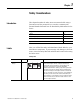
Chapter 1 Safety Considerations Introduction This chapter describes the safety issues encountered while using a linear motor and the precautions you can take to minimize risk. Potential hazards discussed here are identified by labels affixed to the device. Labels Topic Page Labels 9 High Energy Magnets 10 Vertical or Incline Installation 12 Operational Guidelines 13 Here you will find the safety and identification labels affixed to your linear motor components.
Chapter 1 Safety Considerations Identification Labels Title Location Label Coil Name Plate B CAT. NO. LDL-XXXXXXX-XHTXX SERIAL NO. XXXX-X-XXXX www.ab.com Magnet Channel Name Plate Details C This name plate shows the magnet channel catalog number, serial number. CAT. NO. LDL-XXXXXXXXX SERIAL NO. XXXX-X-XXXX www.ab.com RoHS Compliant This name plate shows the coil catalog number, serial number operating voltage and frequency.
Safety Considerations Chapter 1 protective wrapping, cardboard and flux containment plates in place until magnet channel is installed. Clear the inspection and repacking area of any ferrous metals that will attracted to or attract the magnetic assembly. If magnet channels must be unpacked at the same time maintain a distance of 1.5 m (5 ft) between assemblies. Air Freight Restrictions When air freighting linear motor special preparations and precautions must be taken.
Chapter 1 Safety Considerations Vertical or Incline Installation A linear motor driven system mounted vertically or on an incline will not maintain position when the power is removed. Under the influence of gravity the motion platform and its payload will fall to the low end of travel. Design engineers should allow for this by designing in controlled power down circuits or mechanical controls to prevent the linear motor driven system and its payload from being damaged when the power fails.
Safety Considerations Operational Guidelines Chapter 1 Please read and follow the guidelines shown here to safely operate the linear motor created from the these linear motor components. ATTENTION ATTENTION IMPORTANT Observe maximum safe speed. Linear motors are capable of very high forces, accelerations, and speeds. The maximum obtainable acceleration and speed is based on the drive output (bus voltage and current settings).
Chapter 1 Safety Considerations WARNING Large Position Error Tolerances, such as those calculated by the Auto Tune function in RSLogix 5000 programming software, or when configuring a new axis with RSLogix 5000 software, can lead to undetected and repetitive high energy impacts against axis end stops if proper precautions are not in place. These tolerances can also lead to undetected and repetitive high energy impacts against unexpected obstructions.
Chapter 2 Start Introduction 15Publication LDL-UM001A-EN-P - March 2009 Use this chapter to become familiar with the linear motor components, their maintenance needs, and their configuration.
Chapter 2 Start Catalog Number Explanation An ironless linear motor is comprised of a coil and a magnet channel. The following keys show the catalog definition for the linear motors. LDL - x xxx xxx - x x x x x Cable Termination 0 = Flying leads 1 = Circular DIN-Type connector Cable Length 0 = 300 mm (12.45 in.) 1 = 600 mm (23.62 in.) 2 = 1000 mm (39.37 in.
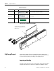
Start Linear Motor Components Chapter 2 Use the diagrams and descriptions to identify the unique components of the linear motor. Components of Ironless Linear Motor Coil and Magnet Channel 1 LDL-N075120-xHT11 Motor Coil Shown 2 LDL- NM075480 Magnet Channel Shown 7 6 GER DAN LDS EA. AR C FIE S ETI THI GN D IN ll to er MA ATE mfu oth LOCbe harrs and ent. Canemakeequipm pacsitive sen 5 4 3 IES SER ww Publication LDL-UM001A-EN-P - March 2009 b. w.a A 00 756 M0 XXX L-N X-X . LD XXXXO .N .
Chapter 2 Start Design Consideration The information provided here is critical to using linear motor components. Design your system to comply with the following points to run safe and successfully. Motor Air Gap Maintaining the air gap is critical to proper installation and operation of the linear motor components. Use the coil, and magnet drawings in Appendix A to calculate the installation envelope dimension.
Start Chapter 2 stops. The following diagram shows a minimal system with mechanical stops. Carriage/Heat Sink Mechanical Stops Mechanical Stops Encoder strip Encoder readhead Linear Encoder Your linear motor components needs to be integrated with a linear encoder purchased from a third party. Carriage/Heat Sink The linear motor coil requires a heat sink to maintain performance. The heat sink requires a minimal mass and surface area as shown on page 62.
Chapter 2 Start Notes: 20 Publication LDL-UM001A-EN-P - March 2009
Chapter 3 Installing the LDL-Series Linear Motor Introduction Unpacking and Inspection The following section shows you how to safely unpack and install your linear motor components. Topic Page Unpacking and Inspection 21 Installing the Linear Motor Components 22 Mount the Magnet Channel 22 Mount the Motor Coil 25 Inspect motor assemblies for damage that may have occurred in shipment. Any damage or suspected damage should be immediately documented.
Chapter 3 Installing the LDL-Series Linear Motor Installing the Linear Motor Components Use the following procedures to install the magnet channel and the motor coil. Required Tools: • Aluminum straight edge • Non-magnetic M4 or M5 hex wrench • Magnet channel alignment tool IMPORTANT TIP The alignment tool is shipped attached to the cables next to the Hall effect module. Remove before operating the linear motor.
Installing the LDL-Series Linear Motor Chapter 3 2. Verify installation envelope dimensions. See table on page 23. Mounting Configuration A Mounting Configuration B Mounting Configuration C W1 0.10 mm (0.003 in.) J 0.83 ±0.30 mm (0.003 ±0.011 in.) Coil Cat. No. Dimension H mm (in.) Magnet Channel Cat. No. Dimension W mm (in.) LDL-x 030xxx-xxxxx 80.0 (3.15) LDL-NM030xxx LDL-NM050xxx 36.4 (1.43) LDL-x 050xxx-xxxxx 100.0 (3.94) LDL-TM030xxx LDL-TM050xxx 37.7 (1.48) LDL-NM075xxx 38.05 (1.
Chapter 3 Installing the LDL-Series Linear Motor 4. Install additional magnet channels. Place a magnet channel on the mounting surface at a distance from the previously installed magnet channel and slide it into position. 2 3 4 5. Align the magnet channels with an aluminum straight edge and the alignment tool and tighten the screws. a. Place the alignment tool in the alignment hole at the butting end of the first two magnet channels. b.
Installing the LDL-Series Linear Motor Chapter 3 Mount the Motor Coil Use M4 x 0.7 screws with a length that extends through the carriage mounting surface by minimum of 5 mm (0.197 in.), but not more than 7 mm (0.276 in.). Follow these steps to mount the motor coil. 1. Clean and remove burrs from the coil mounting surface. 2. Attach the motor coil to the carriage using M4 x 0.7 screw. Lightly tighten the screws. 3. Slide the assembly on to the bearings.
Chapter 3 Installing the LDL-Series Linear Motor 4. Verify the gap between the motor and the magnet channel is 0.83 ±0.30 mm (0.033 ±0.011 in.). Use plastic shim stock and adjust as necessary. Shim 5. Torque the M4 SCHS to 4.6 N•m (3.4 lb•ft) for black oxide steel screw or 3.10 N•m (2.3 lb•ft) for stainless steel screws. 6. Install the bearing fasterners. 7. Secure the assembly using all the mounting holes.
Chapter 4 LDL-Series Linear Motor Connector Data Introduction Linear Motor Coil Connectors This chapter provides power, thermistor, and Hall effect cable connector information for the linear motor coil and Hall effect module. Topic Page Linear Motor Coil Connectors 27 Hall Effect Module Connectors 28 There are two connectors on the linear motor coil, catalog number LDL-xxxxxxxx-xxT11, the power and the Positive Temperature Coefficient (PTC) thermistor.
Chapter 4 LDL-Series Linear Motor Connector Data PTC Thermistor Connector Pin Description Signal 1 Positive Temperature Coefficient (PTC) thermistor + TS+ Positive Temperature Coefficient (PTC) thermistor - TS- – Reserved 3 4 Hall Effect Module Connectors 4 1 3 Mates with PTC thermistor connector on Hall effect module. The following tables show the pinouts the Hall effect module.
LDL-Series Linear Motor Connector Data Chapter 4 PTC Thermistor Connector Pin Description Signal 1 Positive Temperature Coefficient (PTC) thermistor + TS+ 4 Reserved – 3 Positive Temperature Coefficient (PTC) thermistor - TS- 4 3 1 Mates with PTC thermistor connector on linear motor coil.
Chapter 4 LDL-Series Linear Motor Connector Data Notes: 30 Publication LDL-UM001A-EN-P - March 2009
Chapter 5 Wiring the LDL-Series Linear Motor Introduction Connect the Linear Motor Coil This section shows you how to wire your LDL-Series linear motor. Topic Page Connect the Linear Motor Coil 31 Signal and Wire Definitions for Flying Lead Components 33 Making Your Own Extension Cables 34 Mounting and Wiring Two Identical Coils in Tandem 35 Use the following procedure to connect your linear motor, catalog number LDL-xxxxxxx-xHT11. 1.
Chapter 5 Wiring the LDL-Series Linear Motor e. Do not apply excessive force when mating the cable and motor connectors. If the connectors do not go together with light hand force, realign and try again. Power Connector Feedback Connector Encoder Connector Connect your encoder using Encoder Connector Kit, catalog number LDC-ENC-CNCT.
Wiring the LDL-Series Linear Motor Signal and Wire Definitions for Flying Lead Components Chapter 5 For linear motors, catalog numbers LDL-xxxxxxx-xHT20, wire using wiring diagram on page 70. Wire colors and signal types are shown here, for wire gauge information see page 65. Linear Motor Coil The following shows the wire color and signals for the linear motor coil power and PTC thermistor cables, catalog number LDL-xxxxxxx-xxT20.
Chapter 5 Wiring the LDL-Series Linear Motor Hall Effect Module This table shows the signal and wire colors for Hall effect module with flying leads, catalog number LDL-HALL-F. Making Your Own Extension Cables Color Signal Signal Spec Red +V 5…24V DC Hall supply, 20 mA. Black VRTN Hall effect signal common. White S1 – Blue S2 Orange S3 Silver braid Cable shield Terminate at drive end per drive manual instructions.
Wiring the LDL-Series Linear Motor Mounting and Wiring Two Identical Coils in Tandem Chapter 5 This type of installation requires custom motor database file which is available upon request. Contact Application Engineering at 631.344.6600 to request this file. The following tables and diagrams show the wiring and spacing for two identical coils mechanically top mounted(1) to the same plate and driven by one amplifier.
Chapter 5 Wiring the LDL-Series Linear Motor Phase Wiring for Right Exit Power Cables L1 mm (in.) Coil # 1 Master(1) Coil # 2 Slave(2) Amplifier Phase 160 (6.30) Red Red U White White V Black Black W (1) Master has Hall effect module. (2) Slave has no Hall effect module. Cables Exit in the Center If mounting coils in tandem, such that the power cables exit in the center, as shown, use the following table to find mounting distance and phase wiring.
Wiring the LDL-Series Linear Motor Chapter 5 Cables Exit on Opposite Ends If mounting coils in tandem, such that the power cables exit opposite to each other, as shown, use the following table to find mounting distance and phase wiring. Coil #1 is the master Coil #1 Coil #2 Hall Effect Phase Wiring for Opposite End Exit Power Cables L1 mm (in.) Coil # 1 Master(1) Coil # 2 Slave(2) Amplifier Phase 90 (3.54) or 150 (5.
Chapter 5 Wiring the LDL-Series Linear Motor Notes: 38 Publication LDL-UM001A-EN-P - March 2009
Chapter 6 Configure and Start Up the LDL-Series Linear Motor Introduction Before You Begin This section covers the setup and connection verification of a linear motor with either Kinetix 6000, Kinetix 2000, or an Ultra3000 drive.
Chapter 6 Configure and Start Up the LDL-Series Linear Motor Wire the linear encoder such that the position feedback is positive (phase A+ leads phase B+) when the motor is moving in the positive direction. When the motor power and Hall sensor wiring is connected as shown in wiring diagrams in Appendix B, the positive direction of motion is defined as the motor coil moving toward its power cable. This diagram shows positive motion for both a moving coil and a moving magnet channel.
Configure and Start Up the LDL-Series Linear Motor Chapter 6 – For RSLogix 5000 software, version 17.xx or later use Motion Database file, version 5_8_0 or later • Ultra3000 drives – Firmware revision 1.52 or later – Motor Database, motor_03_18_09.mdb or later • Motion Analyzer software, version 4.7 or later Download these files from http://support.rockwellautomation.com. Contact Rockwell Automation Technical Support at 440.646.5800 for assistance.
Chapter 6 Configure and Start Up the LDL-Series Linear Motor Set Up the Connection to Kinetix 6000 or Kinetix 2000 Drive This procedure configures the Kinetix 6000 or Kinetix 2000 drive for your linear motor and encoder combination. For help using RSLogix 5000 software as it applies to setting up your linear motor, refer to Additional Resources on page 7. This procedure assumes you are familiar with RSLogix 5000 software. 1. Click the Driver/Motor tab. 2.
Configure and Start Up the LDL-Series Linear Motor Chapter 6 3. Using the screen image as a reference, configure the parameters as shown in the Setting column. Parameter Setting Comment Loop Configuration Position Servo – Drive Resolution 200 5 µm encoder 500 2 µm encoder 1000 1 µm encoder 2000 0.
Chapter 6 Configure and Start Up the LDL-Series Linear Motor 6. Using the screen image as a reference, configure the parameters as shown in the Setting column. Parameter Setting Comment Feedback Type TTL or Sin/Cos For RSLogix 5000 software,V16 TTL with Hall or Sin/Cos with Hall For RSLogix 5000 software, V17 50 5 µm encoder 125 2 µm encoder 250 1 µm encoder 500 0.
Configure and Start Up the LDL-Series Linear Motor Chapter 6 RSLogix 5000 Software Version 17.00 TTL Encoder RSLogix 5000 Software Version 17.00 Sin/Cos Encoder 7. Click OK to set the values. 8. Click the Units tab. 9. Using the screen image as a reference, configure the parameters as shown in the Setting column. Parameter Setting Position Units mm Average Velocity Timebase 0.25 s You can change position units to inches, or other units, on this tab.
Chapter 6 Configure and Start Up the LDL-Series Linear Motor 10. Click OK to set the values. 11. Click the Conversion tab. 12. Using the screen image as a reference, configure the parameters as shown in the Setting column. Parameter Setting Comment Positioning Mode Linear – Conversion Constant 200 5 µm encoder 500 2 µm encoder 1000 1 µm encoder 2000 0.
Configure and Start Up the LDL-Series Linear Motor Set Up the Connection to an Ultra3000 Drive Chapter 6 This procedure configures the Ultra3000 drive for your linear motor and encoder combination. For help using Ultraware software as it applies to setting up your linear motor, refer to Additional Resources on page 7. This procedure assumes you are familiar with Ultraware software. 1. Open your Motor Configurator Utility. 2. Select the linear motor catalog number. 3. From the Edit menu choose Duplicate.
Chapter 6 Configure and Start Up the LDL-Series Linear Motor 8. Open your Ultraware software. 9. Configure for your Ultra3000 drive. 10. From Workspace select Motor. 11. Click Motor Model and choose the model you created from the pull-down menu. If using an incremental encoder, you are finished. For Sin/Cos encoders continue with steps12 and 13. 12. From Workspace select Encoders. 13. Click Motor Encoder Interpolation and select a value from the pull-down menu.
Configure and Start Up the LDL-Series Linear Motor Verify Motor Encoder Direction Chapter 6 In this section you select controller tag, and use the motor_ActualPostion tag to evaluate the encoder installation. 1. Disable the drive. 2. Note the ActualPostion tag value. 3. Move the axis in the positive direction. See page 39 for definition for positive direction. 4. Verify that the ActualPostion tag value increases as the axis moves.
Chapter 6 Configure and Start Up the LDL-Series Linear Motor Verify Motor Encoder Resolution This test compares the physically measured distance to the distance calculated by the software. It also verifies the encoder setting in the RSLogix 5000 software. 1. Measure and mark a fixed distance of travel on the axis. 2. Record the ActualPosition tag value with carriage at the starting position. 3. Move the carriage to the end position. 4. Record the ActualPosition tag value. 5.
Configure and Start Up the LDL-Series Linear Motor Chapter 6 3. Click OK. 4. Click Test Marker… to run the Test Marker test. See your encoder user documentation for location and frequency of markers. 5. Position the coil so that it can move 60 mm (2.36 in.) in the forward or reverse direction. 6. Click Test Feedback… to run the Test Feedback test. Move the axis by hand at least 60 mm (2.36 in.) when prompted.
Chapter 6 Configure and Start Up the LDL-Series Linear Motor 8. Click the Tune tab. WARNING Large Position Error Tolerances, such as those calculated by the Auto Tune function in RSLogix 5000 programming software, or when configuring a new axis with RSLogix 5000 software, can lead to undetected and repetitive high energy impacts against axis end stops if proper precautions are not in place. These tolerances can also lead to undetected and repetitive high energy impacts against unexpected obstructions.
Configure and Start Up the LDL-Series Linear Motor Chapter 6 10. Click the Homing tab. 11. Choose Sequence to Switch-Marker, or Torque Level-Marker when a repeatable power-up position is desired. Typical linear TTL and Sin/Cos encoders will home repeatability to within one count of resolution when their index mark is used.
Chapter 6 Configure and Start Up the LDL-Series Linear Motor Notes: 54 Publication LDL-UM001A-EN-P - March 2009
Appendix A Specifications and Dimensions Introduction 55Publication LDL-UM001A-EN-P - March 2009 This appendix provides product specifications and mounting dimensions for your LDL-Series ironless linear motor components.
Appendix A Specifications and Dimensions Performance Specifications These tables provide performance specifications for the LDL-Series ironless linear servo motors. Common Performance Specifications These performance specifications apply to all LDL-Series ironless linear servo motors. Attribute Value Motor type 3 phase, wye winding, synchronous permanent magnet stator, non-ventilated linear motor Operating speed, max 10 m/s (32.
Specifications and Dimensions Appendix A LDL-Series Ironless Linear Motor Performance Specifications LDL-Series Ironless Linear Motor (Standard 30 mm frame size) Attribute Units Symbol LDL-N030120-DxTxx LDL-N030240-DxTxx LDL-N030240-ExTxx Force, continuous (1) (2) (3) (4) N (lbf) Fc 63 (14) 126 (28) Force, peak (5) N (lbf) Fp 209 (47) 417 (94) Thermal resistance °C/W Rth 1.73 0.86 Force constant (6) (7) (8) N/Apk (lbf/Apk) Kf 21.0 (4.7) 21.0 (4.7) 42.0 (9.
Appendix A Specifications and Dimensions LDL-Series Ironless Linear Motor (Standard 50 mm frame size) Attribute Units Symbol LDL-N050120-DxTxx LDL-N050240-DxTxx Force, continuous (1) (2) (3) (4) N (lbf) Fc 96 (22) 191 (43) Force, peak (5) N (lbf) Fp 317 (71) 635 (143) Thermal resistance °C/W Rth 1.58 0.79 Force constant (6) (7) (8) N/Apk (lbf/Apk) Kf 35.0 (7.9) 35.0 (7.9) 70.0 (15.7) Back EMF constant p-p (6) (7) (8) Vp/m/s (Vp/in/s) Ke 41.3 (1.1) 41.3 (1.1) 82.7 (2.
Specifications and Dimensions Appendix A LDL-Series Ironless Linear Motor (Thick 50 mm frame size) Attribute Units Symbol LDL-T050120-DxTxx LDL-T050240-DxTxx Force, continuous (1) (2) (3) (4) N (lbf) Fc 110 (25) 220 (49) Force, peak (5) N (lbf) Fp 364 (82) 728 (164) Thermal resistance °C/W Rth 1.19 0.60 Force constant (6) (7) (8) N/Apk (lbf/Apk) Kf 40.2 (9.0) 40.2 (9.0) 80.4 (18.1) Back EMF constant p-p (6) (7) (8) Vp/m/s (Vp/in/s) Ke 47.4 (1.2) 47.4 (1.2) 94.9 (2.
Appendix A Specifications and Dimensions LDL-Series Ironless Linear Motor (Standard 75 mm frame size) Attribute Units Symbol LDL-N075480-DxTxx LDL-N075480-ExTxx Force, continuous (1) (2) (3) (4) N (lbf) Fc 519 (117) Force, peak (5) N (lbf) Fp 1723 (387) Thermal resistance °C/W Rth 0.37 Force constant (6) (7) (8) N/Apk (lbf/Apk) Kf 52.5 (11.8) 105.0 (23.6) Back EMF constant p-p (6) (7) (8) Vp/m/s (Vp/in/s) Ke 62.0 (1.6) 124.0 (3.2) Current, peak (5) (7) Apk (A rms) Ip 32.
Specifications and Dimensions General Specifications Appendix A These tables provide weight, heat sink, environmental for LDL-Series ironless linear motors. Weight Specifications Weight Specifications - Motor Coil with Flying Leads Cat. No. Weight, Approx. Weight, Approx. kg (lb) Cat. No. LDL-N030120-DHT20 0.63 (1.38) LDL-T050240-xHT20 1.71 (3.77) LDL-T030120-DHT20 0.74 (1.64) LDL-N050360-xHT20 2.03 (4.47) LDL-N030240-xHT20 1.14 (2.51) LDL-T050360-xHT20 2.50 (5.52) LDL-T030240-xHT20 1.
Appendix A Specifications and Dimensions Carriage Weight and Heat Sink Area Requirements Cat. No. Required Heat Sink Area cm2 (in.2) Required Carriage Plate Weight kg (lb) LDL-x030120-DHTxx 774 (120) 1.4 (3) LDL-x030240-xHTxx 1160 (180) 2.0 (4.5) LDL-x050120-DHTxx 774 (120) 2.7 (6) LDL-x050240-DHTxx 1160 (180) 4.0 (9) LDL-x050360-DHTxx 1680 (260) 5.9 (13) LDL-x050480-DHTxx 2060 (320) 7.3 (16) LDL-x075480-xHTxx 2060 (320) 7.
Specifications and Dimensions Product Dimensions Publication LDL-UM001A-EN-P - March 2009 Appendix A LDL-Series ironless linear motor components are designed to metric dimensions. Inch dimensions are conversions from millimeters. Untoleranced dimensions are for reference.
G Mounting holes M4 x 0.7 8.5 (0.33), quantity A1. D C B 4.50 (0.177) 35.00 26.00 (1.378) (1.024) 60.00 (2.362) Typical 80.00 (3.150) A 38.00 (1.496) H L F E D B A Mounting holes M4 x 0.7 8.5 (0.33), quantity A1. C 80.00 (3.150) Dimensions for side view of linear motor coil with connectors is identical to this view with flying leads. Refer to table on page 65 for coil mounting surface flatness requirement.
Publication LDL-UM001A-EN-P - March 2009 240.00 (9.449) 240.00 (9.449) – – – – C mm (in.) 320.00 (12.598) 320.00 (12.598) – – – – D mm (in.) 360.00 (14.173) – – – – – E mm (in.) 440.00 (17.323) – – – – – F mm (in.) 420.00 (16.535) 300.00 (11.811) 180.00 (7.087) 60.00 (2.362) 180.00 (7.087) 60.00 (2.362) G mm (in.) 486.00 (19.134) 366.00 (14.409) 246.00 (9.685) 126.00 (4.961) 246.00 (9.685) 126.00 (4.961) H mm (in.) 115.50 (4.547) 90.50 (3.563) 70.50 (2.
106.0 (4.173) 8.00 (0.315) 43.7 (1.72) 20.55 (0.809) 12.57 (0.494) 21.85 (0.860) 1) Tolerance for G dimension is +0.35 mm (+0.012 in.), -0.12 mm (-0.004 in.). 2) Tolerance for L dimension is ±0.25 mm (±0.010 in.). 3) Tolerance for Y dimension is ±0.05 mm (±0 in.002 in.). LDL-TM075480 LDL-TM075120 LDL-NM075480 9.86 (0.388) 479.00 (18.858) 119.00 (4.685) 479.00 (18.858) 119.00 (4.685) 41.1 (1.62) 119.00 (4.685) LDL-NM075120 12.57 (0.494) 20.33 (0.800) 479.00 18.858) 479.00 (18.858) 40.
Appendix B Interconnect Diagrams Introduction This appendix provides wring examples to assist you in wring an LDL-Series linear motors to an Allen-Bradley drive.
Appendix B Interconnect Diagrams Wiring Example for Kinetix 6000 or Kinetix 2000 Drives and LDL-xxxxxxx-xHT11 Linear Motor with a TTL Encoder LDL-Series Linear Motor Coil Kinetix 2000 or Kinetix 6000 IAM (inverter) or AM Module Motor Power (MP) Connector U V W Brown Black 1 2 Blue Green/Yellow 3 4 Three-phase Motor Power GND 2090-CPWM4DF-xxAFxx, 2090-XXNPMF-xxSxx Cable Shield Clamp Note 1 11 Motor Feedback (MF) Connector (IAM/AM) Module A B C 12 13 8 6 14 10 5 4 3 2 1 WHT/Orange Blue N/C WHT/
Interconnect Diagrams Appendix B Wiring Example for Kinetix 6000 or Kinetix 2000 Drives and LDL-xxxxxxx-xHT11 Linear Motor with a Sin/Cos Encoder LDL-Series Linear Motor Coil Kinetix 2000 or Kinetix 6000 IAM (inverter) or AM Module U V Motor Power (MP) Connector W Brown Black 1 2 A B C Blue Green/Yellow 3 4 Three-phase Motor Power GND 2090-CPWM4DF-xxAFxx, 2090-XXNPMF-xxSxx Cable Shield Clamp Note 1 Motor Power Cable Note 2 11 Motor Feedback (MF) Connector (IAM/AM) Module 12 13 8 6 14 10 5 4
Appendix B Interconnect Diagrams Wiring Example for Kinetix 6000 or Kinetix 2000 Drives and LDL-xxxxxxx-xHT20 Linear Motor with a TTL Encoder Kinetix 2000 or Kinetix 6000 IAM (inverter) or AM Module Note 3 LDL-Series Linear Motor Coil Cable Shield Clamp Note 1 Motor Feedback (MF) Connector (IAM/AM) Module W V U 1 W V U Black W Three-phase White V GND Motor Power Red U TS+ TS - Black Black Thermal Switch Power Red White S1 Blue S2 Orange S3 COM Black 11 12 13 8 1 2 3 4 5 10 14 6 Hall Ef
Interconnect Diagrams Appendix B Wiring Example for Kinetix 6000 or Kinetix 2000 Drives and LDL-xxxxxxx-xHT20 Linear Motor with a Sin/Cos Encoder Kinetix 2000 or Kinetix 6000 IAM (inverter) or AM Module LDL-Series Linear Motor Coil Cable Shield Clamp Note 1 Motor Feedback (MF) Connector (IAM/AM) Module W V U 1 W V U Black W White V Red U TS+ TS - Black Black Three-phase GND Motor Power Thermal Switch Power Red White S1 Blue S2 Orange S3 COM Black 11 12 13 8 1 2 3 4 5 10 14 6 Hall Effec
Appendix B Interconnect Diagrams Wiring Example for Ultra Drive and LDL-xxxxxxx-xHT11 Linear Motor with a TTL Encoder LDL-Series Linear Motor Coil LDL-Series Linear Motor Coil Ultra3000 Drive U V Motor Power (TB1) Connector W Brown Black 1 2 A B C Blue Green/Yellow 3 4 Three-phase Three-phase Motor Power Motor Power GND 2090-CPWM4DF-xxAFxx, 2090-XXNPMF-xxSxx Cable Shield Clamp Note 1 11 12 13 8 Motor Feedback (CN2) Connector 6 14 10 5 4 3 2 1 Motor Power Cable 2 Cable MotorNote Power WHT/Ora
Interconnect Diagrams Appendix B Wiring Example for Ultra3000 Drive and LDL-xxxxxxx-xHT11 Linear Motor with a Sin/Cos Encoder LDL-Series Linear Motor Coil Ultra3000 Drive Motor Power (TB1) Connector U V W Brown Black 1 2 A B C Blue Green/Yellow 3 4 Three-phase Motor Power GND 2090-CPWM4DF-xxAFxx, 2090-XXNPMF-xxSxx Cable Shield Clamp Note 1 11 12 13 8 Motor Feedback (CN2) Connector 6 14 10 5 4 3 2 1 WHT/Orange Blue N/C WHT/Blue Yellow WHT/Yellow Motor Power Cable Note 2 TS+ N/C WHT/Gray T
Appendix B Interconnect Diagrams Ultra3000 Drive LDL-Series Linear Motor Coil Cable Shield Clamp Note 1 W V U 1 Black W Three-phase White V GND Motor Power Red U TS+ TS - Black Black Thermal Switch Power Red White S1 Blue S2 Orange S3 COM Black 11 12 13 8 1 2 3 4 5 10 14 6 Motor Feedback (CN2) Connector W V U Hall Effect Module AM+ AMBM+ BMIM+ IMPOWER COM Wire as shown here using cable type appropriate for your application.
Interconnect Diagrams Appendix B Wiring Example for Ultra3000 Drive and LDL-xxxxxxx-xHT20 Linear Motor with a Sin/Cos Encoder Ultra3000 Drive LDL-Series Linear Motor Coil Cable Shield Clamp Note 1 W V U 1 Black W Three-phase White V GND Motor Power Red U TS+ TS - Black Black Thermal Switch Power Red White S1 Blue S2 Orange S3 COM Black 11 12 13 8 1 2 3 4 5 10 14 6 Motor Feedback (CN2) Connector W V U Hall Effect Module COS+ COSSIN+ SINIM+ IMPOWER COM Wire as shown here using cable type
Appendix B Interconnect Diagrams Notes: 76 Publication LDL-UM001A-EN-P- March 2009
Appendix C Sin/Cos Linear Encoder and Kinetix 6000 Drives Introduction Kinetix 6000 Drive Feedback Connection This appendix guides you through commissioning a linear motor with a Sin/Cos 1V peak-to-peak output linear encoder.
Appendix C Sin/Cos Linear Encoder and Kinetix 6000 Drives Encoder Counting Direction Normally, the encoder signals will output sine-leads-cosine (AM leads BM) when the linear encoder head is moving towards its cable, relative to the encoder scale. SERCOS drives count this in a negative direction. Set Up the Axis Properties When installing a Sin/Cos linear encoder, setup the Axis Property tabs by doing the following. 1. Click the Motor Feedback tab. 2. Enter the following parameters.
Sin/Cos Linear Encoder and Kinetix 6000 Drives Appendix C 3. Click the Drive/Motor tab. 4. Enter the following parameters. Parameter Value Comment Driver Resolution 25600 For 40 µ pitch encoder scale. 51200 For 20 µ pitch encoder scale. Motor Millimeter – Drive Counts per 5. Click the Conversion tab. 6. Enter the following parameters. Publication LDL-UM001A-EN-P - March 2009 Parameter Value Comment Driver Resolution 25600 For 40 µ pitch encoder scale.
Appendix C Sin/Cos Linear Encoder and Kinetix 6000 Drives Notes: 80 Publication LDL-UM001A-EN-P - March 2009
Index A air gap 18, 26 alignment tool 22, 24 aluminum straight edge 22 attraction 22 Automatic 21 automatic implantable cardioverter defibrillator (AICD) 9 B beryllium copper 22 bulk head connector kit 31 bumper 12, 18 burn hazard 12 bus voltage, applied 56 C carriage 19 certifications 62 cogging torque 56 coil 17 coil power connector 27 coil weight connectorized 61 flying lead 61 commission Kinetix 2000 drive 42 Kinetix 6000 drive 42 Ultra-3000 drive 47 common specification 56 connector 27 encoder 17, 29
Index length 16 linear encoder 19 M magnet channel 16, 17, 22 alignment 24 alignment tool 24 maintenance 19 max. speed 13 max.
Index thick 30 mm frame 57 thick 50 mm frame 59 thick 75 mm frame 60 storage 19 T tandem motors 35 temperature max heat sink 12 Thermal 56 thermal time constant 56 time constant 56 tools 22 torque magnet channel 22 U unpacking 21 V Publication LDL-UM001A-EN-P - March 2009 verify direction 49 motor wiring 50 resolution 50 W warning air freight restrictions 11 automatic implantable cardioverter defibrillator (AICD) 9 powerful forces 9 weight coil flying lead 61 magnet channel 61 wiring 31 wiring diagra
Rockwell Automation Support Rockwell Automation provides technical information on the Web to assist you in using its products. At http://support.rockwellautomation.com, you can find technical manuals, a knowledge base of Faqs, technical and application notes, sample code and links to software service packs, and a MySupport feature that you can customize to make the best use of these tools.