
Manual
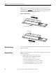
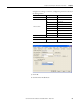
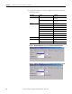
Table Of Contents
- Summary of Changes
- Table of Contents
- Preface
- Chapter 1
- Chapter 2
- Chapter 3
- Install the LDC-Series Linear Motor
- Introduction
- Unpacking and Inspection
- Installing Linear Motor Components
- Required Tools
- Mount a Single Coil with Multiple Magnet Tracks
- 1. Clear the magnet track mounting surface of foreign material.
- 2. Verify the flatness of the surface to which the magnet track is to be mounted.
- 3. Verify the dimension of the opening for the magnet track, coil, and cooling plate if used.
- 4. Remove all burrs and clean the motor coil mounting surface.
- 5. Position the carriage toward the end of travel where you want the cable to exit.
- 6. Install the motor under the carriage, using M5 x 0.8 bolts that extend through the slide by at least 12 mm (0.5 in.), but no more then 20 mm (0.7 in.).
- 7. Tighten the screws but do not torque.
- 8. On the opposite end of the base, install the first magnet track using M5 x 0.8 x 16 mm Socket Head Captive Screw (SHCS).
- 9. Install additional magnet tracks.
- 10. Move the carriage with motor coil installed over the installed magnet tracks.
- 11. Measure the gap between the motor coil and magnet track using plastic shim stock.
- 12. Install the remaining magnet tracks in the order shown.
- 13. Slightly loosen the mounting screws on the exposed magnet tracks.
- 14. Align the magnet tracks with an aluminum straight edge, and the supplied alignment tool.
- 15. Place the alignment tool in the holes on each of the magnet tracks.
- 16. Align the edges of the magnet tracks with the aluminum straight edge and tighten the bolts.
- 17. Position the carriage over the complete sections and continue aligning the remainder of the magnet tracks.
- 18. Torque all screws to the values listed in the table, securing assemblies in place by using all mounting holes.
- Mount a Single Coil with a Single Magnet Track
- 1. Install the magnet track by using M5 x 0.8 x 16 mm SHCS.
- 2. Remove any burrs and clean the motor-coil mounting surface.
- 3. Install the motor coil under the carriage, by using M5 x 0.8 screws that extend through the carriage by at least 12 mm (0.5 in.), but no more than 20 mm (0.7 in.).
- 4. Tighten screws but do not torque them.
- 5. Slide the carriage assembly onto the bearing pucks.
- 6. Attach the carriage assembly to the bearing pucks.
- 7. Measure the gap between the motor and magnet by using plastic shim stock.
- 8. Torque all screws to the values listed in the table, securing assemblies in place by using all mounting holes.
- Notes:
- Install the LDC-Series Linear Motor
- Chapter 4
- Chapter 5
- Wire the LDC-Series Linear Motor
- Introduction
- Connect the Linear Motor Coil
- Signal and Wire Definitions for Flying Lead Components
- Making Your Own Extension Cables
- Mounting and Wiring Two Identical Coils in Tandem
- Wire the LDC-Series Linear Motor
- Chapter 6
- Configure and Start Up the LDC-Series Linear Motor
- Introduction
- Before You Begin
- What You Need
- Required Files
- Follow These Steps
- Update the Linear Motor Database
- Set Up the Connection to a Kinetix 6000, Kinetix 6500/ 6200, or Kinetix 2000 Drive
- 1. Click the Driver/Motor tab.
- 2. Click Change Catalog and select the appropriate motor catalog number from the following list.
- 3. Click OK.
- 4. Click the Motor Feedback tab.
- 5. Using the screen image as a reference, configure the parameters as shown in the Setting column.
- 6. Click OK to sets the values.
- 7. Click the Units tab.
- 8. Using the screen image as a reference, configure the parameters as shown in the Setting column.
- 9. Click OK to set the values.
- 10. Click the Conversion tab.
- 11. Using the screen image as a reference, configure the parameters as shown in the Setting column.
- 12. Click OK.
- Set Up the Connection to an Ultra3000 Drive
- 1. Open your Motor Configurator Utility.
- 2. Select the linear motor catalog number.
- 3. From the Edit menu, choose Duplicate.
- 4. Rename the Model.
- 5. Click Encoder Type and select either Incremental or Sin/Cos.
- 6. Click Lines Per Meter and enter the value.
- 7. Click Close.
- 8. Open your Ultraware software.
- 9. Configure your Ultra3000 drive.
- 10. From the Workspace dialog box, select Motor.
- 11. Click Motor Model.
- 12. Choose the model you created from the pull-down menu.
- 13. From the Workspace dialog box, select Encoders.
- 14. Click Motor Encoder Interpolation.
- 15. Select a value from the pull-down menu.
- Verify Motor Encoder Direction
- 1. Disable the drive.
- 2. Note the ActualPostion tag value.
- 3. Move the axis in the positive direction.
- 4. Verify that the ActualPostion tag value increases as the axis moves. If the positive direction of travel does not match what has been defined by the motor power and Hall Sensing wiring, then change the direction by rewiring the encoder by using th...
- Verify Motor Encoder Resolution
- 1. Measure and mark a fixed distance of travel on the axis.
- 2. Record the ActualPosition tag value with carriage at the starting position.
- 3. Move the carriage to the end position.
- 4. Record the ActualPosition tag value.
- 5. Calculate the distance moved by using the record values.
- 6. Compare the actual distance and the calculated distance.
- Verify Linear Motor Wiring and Function
- 1. Click the Hookup tab.
- 2. Configure the parameters.
- 3. Click OK.
- 4. Click Test Marker.
- 5. Position the coil so that it can move 60 mm (2.36 in.) in the forward or reverse direction.
- 6. Click Test Feedback.
- 7. Click Test Command & Feedback.
- 8. Click the Tune tab.
- 9. Configure the parameters in the Tune tab as suggested in the Initial Setting column, leaving all other tune options off for your first pass.
- 10. Click the Homing tab.
- 11. From the Sequence pull-down menu, choose Switch-Marker, or Torque Level-Marker when a repeatable power-up position is desired.
- Additional Adjustments for Cooling Plate Option
- Configure and Start Up the LDC-Series Linear Motor
- Appendix A
- Appendix B
- Appendix C
Rockwell Automation Publication LDC-UM001B-EN-P - March 2011 45
Chapter
6
Configure and Start Up the LDC-Series Linear
Motor
Introduction
This section covers the set up and connection verification of a linear motor with
either Kinetix 6000, Kinetix 6500/6200, Kinetix 2000, or Ultra3000 drives.
Before You Begin
This chapter assumes you have wired your linear motor and Allen-Bradley drive
as shown in wiring diagrams in Appendix A
starting on page 61.
Motor Direction Defined
Positive motion is dependent on encoder orientation, encoder wiring, and coil or
magnet track motion.
Most linear encoders are attached to the motor coil with the encoder cable facing
the same direction as the motor coil cable.
Wire the linear encoder such that the position feedback is positive (phase A+
leads phase B+) when the motor is moving in the positive direction.
Topic Pages
Before You Begin 45
What You Need 46
Required Files 46
Follow These Steps 47
Update the Linear Motor Database 47
Set Up the Connection to a Kinetix 6000, Kinetix 6500/6200, or Kinetix 2000 Drive 48
Set Up the Connection to an Ultra3000 Drive 53
Verify Motor Encoder Direction 55
Verify Motor Encoder Resolution 56
Verify Linear Motor Wiring and Function 56
IMPORTANT
It is important that the brushless linear motor coil, Hall sensor, and the
linear encoder be wired correctly for proper drive commutation and servo
operation to get positive motion when commutated.
Please read and understand Motor Direction Defined
.