
Manual
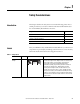
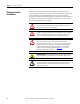

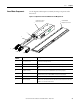
Table Of Contents
- Summary of Changes
- Table of Contents
- Preface
- Chapter 1
- Chapter 2
- Chapter 3
- Install the LDC-Series Linear Motor
- Introduction
- Unpacking and Inspection
- Installing Linear Motor Components
- Required Tools
- Mount a Single Coil with Multiple Magnet Tracks
- 1. Clear the magnet track mounting surface of foreign material.
- 2. Verify the flatness of the surface to which the magnet track is to be mounted.
- 3. Verify the dimension of the opening for the magnet track, coil, and cooling plate if used.
- 4. Remove all burrs and clean the motor coil mounting surface.
- 5. Position the carriage toward the end of travel where you want the cable to exit.
- 6. Install the motor under the carriage, using M5 x 0.8 bolts that extend through the slide by at least 12 mm (0.5 in.), but no more then 20 mm (0.7 in.).
- 7. Tighten the screws but do not torque.
- 8. On the opposite end of the base, install the first magnet track using M5 x 0.8 x 16 mm Socket Head Captive Screw (SHCS).
- 9. Install additional magnet tracks.
- 10. Move the carriage with motor coil installed over the installed magnet tracks.
- 11. Measure the gap between the motor coil and magnet track using plastic shim stock.
- 12. Install the remaining magnet tracks in the order shown.
- 13. Slightly loosen the mounting screws on the exposed magnet tracks.
- 14. Align the magnet tracks with an aluminum straight edge, and the supplied alignment tool.
- 15. Place the alignment tool in the holes on each of the magnet tracks.
- 16. Align the edges of the magnet tracks with the aluminum straight edge and tighten the bolts.
- 17. Position the carriage over the complete sections and continue aligning the remainder of the magnet tracks.
- 18. Torque all screws to the values listed in the table, securing assemblies in place by using all mounting holes.
- Mount a Single Coil with a Single Magnet Track
- 1. Install the magnet track by using M5 x 0.8 x 16 mm SHCS.
- 2. Remove any burrs and clean the motor-coil mounting surface.
- 3. Install the motor coil under the carriage, by using M5 x 0.8 screws that extend through the carriage by at least 12 mm (0.5 in.), but no more than 20 mm (0.7 in.).
- 4. Tighten screws but do not torque them.
- 5. Slide the carriage assembly onto the bearing pucks.
- 6. Attach the carriage assembly to the bearing pucks.
- 7. Measure the gap between the motor and magnet by using plastic shim stock.
- 8. Torque all screws to the values listed in the table, securing assemblies in place by using all mounting holes.
- Notes:
- Install the LDC-Series Linear Motor
- Chapter 4
- Chapter 5
- Wire the LDC-Series Linear Motor
- Introduction
- Connect the Linear Motor Coil
- Signal and Wire Definitions for Flying Lead Components
- Making Your Own Extension Cables
- Mounting and Wiring Two Identical Coils in Tandem
- Wire the LDC-Series Linear Motor
- Chapter 6
- Configure and Start Up the LDC-Series Linear Motor
- Introduction
- Before You Begin
- What You Need
- Required Files
- Follow These Steps
- Update the Linear Motor Database
- Set Up the Connection to a Kinetix 6000, Kinetix 6500/ 6200, or Kinetix 2000 Drive
- 1. Click the Driver/Motor tab.
- 2. Click Change Catalog and select the appropriate motor catalog number from the following list.
- 3. Click OK.
- 4. Click the Motor Feedback tab.
- 5. Using the screen image as a reference, configure the parameters as shown in the Setting column.
- 6. Click OK to sets the values.
- 7. Click the Units tab.
- 8. Using the screen image as a reference, configure the parameters as shown in the Setting column.
- 9. Click OK to set the values.
- 10. Click the Conversion tab.
- 11. Using the screen image as a reference, configure the parameters as shown in the Setting column.
- 12. Click OK.
- Set Up the Connection to an Ultra3000 Drive
- 1. Open your Motor Configurator Utility.
- 2. Select the linear motor catalog number.
- 3. From the Edit menu, choose Duplicate.
- 4. Rename the Model.
- 5. Click Encoder Type and select either Incremental or Sin/Cos.
- 6. Click Lines Per Meter and enter the value.
- 7. Click Close.
- 8. Open your Ultraware software.
- 9. Configure your Ultra3000 drive.
- 10. From the Workspace dialog box, select Motor.
- 11. Click Motor Model.
- 12. Choose the model you created from the pull-down menu.
- 13. From the Workspace dialog box, select Encoders.
- 14. Click Motor Encoder Interpolation.
- 15. Select a value from the pull-down menu.
- Verify Motor Encoder Direction
- 1. Disable the drive.
- 2. Note the ActualPostion tag value.
- 3. Move the axis in the positive direction.
- 4. Verify that the ActualPostion tag value increases as the axis moves. If the positive direction of travel does not match what has been defined by the motor power and Hall Sensing wiring, then change the direction by rewiring the encoder by using th...
- Verify Motor Encoder Resolution
- 1. Measure and mark a fixed distance of travel on the axis.
- 2. Record the ActualPosition tag value with carriage at the starting position.
- 3. Move the carriage to the end position.
- 4. Record the ActualPosition tag value.
- 5. Calculate the distance moved by using the record values.
- 6. Compare the actual distance and the calculated distance.
- Verify Linear Motor Wiring and Function
- 1. Click the Hookup tab.
- 2. Configure the parameters.
- 3. Click OK.
- 4. Click Test Marker.
- 5. Position the coil so that it can move 60 mm (2.36 in.) in the forward or reverse direction.
- 6. Click Test Feedback.
- 7. Click Test Command & Feedback.
- 8. Click the Tune tab.
- 9. Configure the parameters in the Tune tab as suggested in the Initial Setting column, leaving all other tune options off for your first pass.
- 10. Click the Homing tab.
- 11. From the Sequence pull-down menu, choose Switch-Marker, or Torque Level-Marker when a repeatable power-up position is desired.
- Additional Adjustments for Cooling Plate Option
- Configure and Start Up the LDC-Series Linear Motor
- Appendix A
- Appendix B
- Appendix C
Rockwell Automation Publication LDC-UM001B-EN-P - March 2011 15
Safety Considerations Chapter 1
Operational Guidelines
Please read and follow the guidelines shown here to safely operate the linear
motor created from these linear motor components.
ATTENTION: Observe maximum safe speed. Linear motors are capable
of very high forces, accelerations, and speeds. The maximum obtainable
acceleration and speed is based on the drive output (bus voltage and
current settings). The allowable maximum speed is application specific
and partly based on the linear motion mechanics supplied by others.
ATTENTION: Moving parts can cause injury. Before operating the linear
motor, make sure all components are secure and magnet mounting
hardware is below the magnet surface. Remove all unused parts from the
motor travel assembly to prevent them from jamming in the motor air gap
and damaging the coil or flying off and causing bodily injury.
IMPORTANT
You are responsible for making sure the servo control system safely
controls the linear motor with regards to maximum safe force,
acceleration, and speed, including runaway conditions.
A runaway condition can be caused by incorrect motor, hall effect, and
position feedback wiring resulting in violent uncontrolled motion.
ATTENTION: Keep away from the line of motor travel at all times.
Always have bumpers in place and securely fastened before applying
power to your linear motor.
ATTENTION: High voltage can kill. Do not operate with exposed wires.
Do not go near electrically live parts.
ATTENTION: Large Position Error Tolerances, such as those calculated by
the Auto Tune function in RSLogix 5000 programming software, or when
configuring a new axis with RSLogix 5000 software, can lead to
undetected and repetitive high energy impacts against axis end stops if
proper precautions are not in place. These tolerances can also lead to
undetected and repetitive high energy impacts against unexpected
obstructions. Such impacts can lead to equipment damage and/or serious
injury.
To identify the safety concerns that you have with default Position Error
Tolerance or after an Auto-Tune Function go to the Rockwell Automation
Knowlegebase. Click Find Technical Support Answers and search for
Answer Id 55937.