Installation Instructions LDAT-Series Integrated Linear Thrusters Catalog Numbers LDAT Frame 30 LDAT Frame 50 LDAT Frame 75 LDAT Frame 100 LDAT Frame 150 LDAT-S03xxxx-DB LDAT-S05xxxx-DB LDAT-S07xxxx-DB LDAT-S10xxxx-DB LDAT-S15xxxx-DB LDAT-S03xxxx-DBS LDAT-S05xxxx-DBS LDAT-S07xxxx-DBS LDAT-S10xxxx-DBS LDAT-S15xxxx-DBS LDAT-S03xxxx-EB LDAT-S05xxxx-EB LDAT-S07xxxx-EB LDAT-S10xxxx-EB LDAT-S15xxxx-EB LDAT-S03xxxx-EBS LDAT-S05xxxx-EBS LDAT-S07xxxx-EBS LDAT-S10xxxx-EBS LDAT-S15xxxx-EBS LD
LDAT-Series Integrated Linear Thrusters Important User Information Solid state equipment has operational characteristics differing from those of electromechanical equipment. Safety Guidelines for the Application, Installation and Maintenance of Solid State Controls, publication SGI-1.1, available from your local Rockwell Automation® sales office or online at http://www.rockwellautomation.
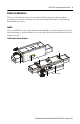
LDAT-Series Integrated Linear Thrusters 3 Safety Considerations This section describes the safety issues encountered while using a linear thruster and the precautions you can take to minimize risk. Potential hazards discussed here are identified by labels affixed to the device. Labels Here you will find the safety and identification labels affixed to your linear thruster. To prevent injury and damage to the linear thruster, review the safety label and its details and location before using the actuator.
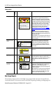
LDAT-Series Integrated Linear Thrusters Title Location Safety Labels Strong Magnets A Label Details WARNING High magnetic field exerts strong forces. Pacemaker and ICD wearers maintain minimum of 300 mm distance. Tools, metal objects and surfaces can be attracted and cut, pinch or entrap hands and fingers. Pitch Point/ Motion Hazard B CAUTION Sudden machine motion can cause injury. Stand clear when machine is in motion. Pitch point. Keep clear during operation.
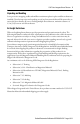
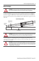
LDAT-Series Integrated Linear Thrusters 5 Unpacking and Handling Leave protective wrapping, cardboard and flux containment plates in place until linear thruster is installed. Clear the inspection and repacking area of any ferrous metals that will be attracted to or attract the linear thruster. If you are working multiple linear thrusters, maintain a distance of 1.5 m (5 ft) between each linear thruster.
LDAT-Series Integrated Linear Thrusters Vertical or Incline Installation A linear thruster driven system mounted vertically or on an incline will not maintain position when the power is removed. Under the influence of gravity the motion platform and its payload will fall to the low end of travel. Design engineers should allow for this by designing in controlled power down circuits or mechanical controls to prevent the linear thruster driven system and its payload from being damaged when the power fails.
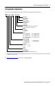
LDAT-Series Integrated Linear Thrusters 7 Catalog Number Explanation This is the catalog explanation for the LDAT-Series integrated linear thruster. LDAT - x xx x xxx - x x x x x Lubrication Blank = Standard Bearing Seal Blank = Standard Bearing Protection Blank = No Cover S = Strip Cover Encoder Type B = Incremental, magnetic scale, 5 μm resolution D = Absolute, magnetic scale, hiperface (1) Winding D = High Speed E = Low Speed Travel 010 = 100 mm (3.94 in.) 060 = 600 mm (23.62 in.) 020 = 200 mm (7.
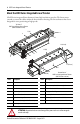
LDAT-Series Integrated Linear Thrusters About the LDAT-Series Integrated Linear Thruster LDAT-Series integrated linear thrusters feature high resolution encoders. The linear motor extends or retracts the slider within the linear thruster housing. The linear thrusters have been designed for exact positioning at high speeds.
LDAT-Series Integrated Linear Thrusters 9 Before You Begin ATTENTION: To avoid personal injury and structural damage to the linear thruster, never attempt lift or move the linear thruster by any means other than those listed in this publication. Keep the packaging material on the linear thruster to minimize the possibility of it tipping. Do not remove any of the corrugated or foam inserts until the linear thruster is at the installation area.
LDAT-Series Integrated Linear Thrusters Planning Your Installation Refer to the Kinetix Linear Motion Specifications GMC-TD002, for the specifications and additional products referenced in this section: • Include unobstructed access to the linear thrusters shipping and handling setscrew in your application design. • This product can be operated in compliance with the relevant safety regulations, only if the maximum loading limits are observed.
LDAT-Series Integrated Linear Thrusters 11 Remove the Linear Thruster from the Shipping Container 1. Consider the weight of the linear thruster. Depending on the design, the linear thruster can weigh up to 106.7 kg (235.2 lb). ATTENTION: Linear thrusters that exceed 22.7 kg (50.0 lb) require a two man lift. Do not lift the linear thruster by the slider. Use supplied eye bolts when ever possible. 2. Attach two eye bolts to connector side of the linear thruster. 3.
LDAT-Series Integrated Linear Thrusters Prolonging Linear Thruster Life Thoughtful design and proper maintenance can increase the life of a linear thruster. Follow these guidelines to maximize the life of a linear thruster especially within a food processing environment: • Always provide a drip loop in each cable to carry liquids away from the connection to the motor.
LDAT-Series Integrated Linear Thrusters 13 ATTENTION: Unmounted linear thrusters, disconnected mechanical couplings, and disconnected cables are dangerous if power is applied. Appropriately identify (tag-out) disassembled equipment, and restrict (lock-out) access to electrical power. Failure to observe these safety precautions could result in personal injury. Follow these steps to prepare the linear thruster for installation on the machine. 1.
LDAT-Series Integrated Linear Thrusters If installing a counterbalance kit, install counter balance end bracket between slider end cap and slider-end accessory. Complete counter balance kit installation by following steps in Install Counterbalance Kit on page 14. Install Counterbalance Kit Follow these steps to install the counter balance kit. Unless otherwise noted, torque specifications have a ±20% tolerance. 1. Remove M8 set screws from stator body. 2. Install stator bracket with two M8 x 1.
LDAT-Series Integrated Linear Thrusters 15 6. Install the counter balance and slider-end cap the screws that came with the kit. 7. Torque to values shown in table. LDAT Frame Size S1 S1 Torque N•m (lb•in) S2 S2 Torque N•m (lb•in) 30 M8 x1.25 x 40 13.5 (10.0) M6 x1.0 x 30 9.0 (6.6) M10 x1.5 x 50 33.9 (25.0) M10 x1.5 x 30 33.9 (25.0) 100 M12 x1.75 x 60 54.8 (40.4) 150 M14 x2.05 x 60 84.7 (62.5) 50 75 8. Screw one 3/8 in. hex nut onto a spring anchor. 9.
LDAT-Series Integrated Linear Thrusters Install with Clevis Mount Accessory Install the clevis mount accessory with screws included in the kit and torque to the values shown. Cat. No. Clevis Kit LDAT-S03 LDAT-03-CLVSM or LDAT-03-CLVSF LDAT-S05 LDAT-0507-CLVSM or LDAT-0507-CLVSF LDAT-S07 LDAT-S10 LDAT-S15 Torque, max 6.8 N•m (5.00 lb•ft) LDAT-1015-CLVSM or LDAT-1015-CLVSF 14.7 N•m (10.
LDAT-Series Integrated Linear Thrusters 17 Direct Mount the Linear Thruster Follow these steps to mount the linear thruster on directly on your machine. 1. Verify the mounting surface flatness. The mounting surface must be flat or shimmed flat to the mounting surface of the linear thruster within 0.127 mm (0.005 in.) to avoid distortion and damage to the actuator housing. 2. Install and evenly tighten the steel fasteners so the linear thruster. Torque the steel fasteners evenly to following values. Cat.
LDAT-Series Integrated Linear Thrusters The cable length from the linear thruster to the drive should be limited to 10 m (32.8 ft). If longer cables are necessary, a 1321-3Rx-x series line reactor is required. Refer to the 1321 Power Conditioning Products Technical Data, publication 1321- TD001, to choose a line reactor for applications requiring cable longer than 10 m (32.8 ft). Attach Motor Cables Use this procedure to attach the power and feedback cables after the linear thruster is mounted. 1.
LDAT-Series Integrated Linear Thrusters 19 ATTENTION: Make sure cables are installed and restrained to prevent uneven tension or flexing at the cable connectors. Excessive and uneven lateral force at the cable connectors may result in the connector’s environmental seal opening and closing as the cable flexes. Failure to observe these safety precautions could result in damage to the linear thruster motor and its components. 3. Form a drip loop in the cable to keep liquids away from the connectors. 4.
55.00 (2.17) C Rockwell Automation Publication LDAT-IN001A-EN-P - August 2012 55.00 (2.17) B A 32.50 (1.28) Square 53.85 (2.120) 66.35 (2.612) 46.35 (1.82) To Stop (1) Typical both ends LDAT-MID-FTMOUNT optional foot mounting uses (4X) M8 x 1.25 x 20, min socket head cap screws. M LDAT-MID-FTMOUNT optional foot mounting uses (4X) M8 x1.25 x 20 min socket head cap screw. Shipping/ Handling Lockscrew A L M 25.10 (0.99) 130.00 (5.12) 165.00 (6.50) 14.56 (0.57) Typical 174.03 (6.85) 125.
300 (11.8) 400 (15.7) LDAT-S033030-xxx LDAT-S033040-xxx 200 (7.9) LDAT-S033020-xxx 300 400 (15.7) 100 (3.9) LDAT-S032040-xxx LDAT-S033010-xxx 300 (11.8) LDAT-S032030-xxx 200 (7.9) LDAT-S032020-xxx 200 400 (15.7) 100 (3.9) LDAT-S031040-xxx LDAT-S032010-xxx 300 (11.8) LDAT-S031030-xxx 200 (7.9) 100 LDAT-S031020-xxx Stroke mm (in.) 100 (3.9) Motor size (reference) LDAT-S031010-xxx Linear Thruster (frame 30) Cat. No. Dimensions (frame 30) 925.4 (36.43) 825.4 (32.50) 725.4 (28.
Rockwell Automation Publication LDAT-IN001A-EN-P - August 2012 70.00 (2.76) B 60.00 (2.36) Typical C A A 38.00 (1.50) Square 53.85 (2.120) 66.35 (2.612) 49.53 (1.95) To Stop (1) Typical both ends LDAT-MID-FTMOUNT optional foot mounting uses (4X) M8 x 1.25 x 20, min socket head cap screws. M LDAT-MID-FTMOUNT optional foot mounting uses (4X) M8 x 1.25 x 20, min socket head cap screws. Shipping/ Handling Lockscrew M L 142.00 160.00 (5.59) (6.30) ATTENTION: High magnetic field.
400 (15.7) 500 (19.7) LDAT-S054040-xxx 200 (7.9) 300 (11.8) LDAT-S054020-xxx LDAT-S054030-xxx LDAT-S054050-xxx 500 (19.7) 100 (3.9) LDAT-S053050-xxx LDAT-S054010-xxx 400 300 (11.8) 400 (15.7) LDAT-S053040-xxx 300 100 (3.9) 200 (7.9) LDAT-S053010-xxx LDAT-S053020-xxx LDAT-S053030-xxx 400 (15.7) 500 (19.7) LDAT-S052040-xxx 200 (7.9) 300 (11.8) LDAT-S052020-xxx LDAT-S052030-xxx LDAT-S052050-xxx 500 (19.7) 100 (3.9) LDAT-S051050-xxx LDAT-S052010-xxx 200 300 (11.8) 400 (15.
100 (3.9) 200 (7.9) 300 (11.8) 400 (15.7) LDAT-S072010-xxx LDAT-S072020-xxx LDAT-S072030-xxx LDAT-S072040-xxx Rockwell Automation Publication LDAT-IN001A-EN-P - August 2012 700 (27.6) 400 (15.7) LDAT-S073040-xxx LDAT-S073070-xxx 300 (11.8) LDAT-S073030-xxx 600 (23.6) 200 (7.9) LDAT-S073020-xxx 500 (19.7) 100 (3.9) LDAT-S073010-xxx LDAT-S073060-xxx 700 (27.6) LDAT-S072070-xxx LDAT-S073050-xxx 600 (23.6) LDAT-S072060-xxx 300 500 (19.7) LDAT-S072050-xxx 200 Stroke mm (in.
700 (27.6) 400 (15.7) LDAT-S076040-xxx 600 (23.6) 300 (11.8) LDAT-S076030-xxx LDAT-S076070-xxx 200 (7.9) LDAT-S076020-xxx LDAT-S076060-xxx 100 (3.9) LDAT-S076010-xxx 500 (19.7) 700 (27.6) LDAT-S074070-xxx LDAT-S076050-xxx 600 (23.6) 600 500 (19.7) LDAT-S074060-xxx 400 (15.7) LDAT-S074040-xxx LDAT-S074050-xxx 300 (11.8) LDAT-S074030-xxx 400 100 (3.9) 200 (7.9) LDAT-S074010-xxx LDAT-S074020-xxx Stroke mm (in.) Linear Thruster Motor size (frame 75) Cat. No.
53.85 (2.120) A Rockwell Automation Publication LDAT-IN001A-EN-P - August 2012 66.35 (2.612) Typical A 52.70 (2.075) To Stop (1) Typical both ends LDAT-LARGE-FTMOUNT optional foot mounting uses quanitity S M10 x 1.5 x 20 min socket head cap screw. 62.00 (2.441) Typical M 56.50 (2.224) Square Shipping/ Handling Lockscrew M L 162.00 (6.378) 212.00 (8.346) 230.00 (9.055) 1/2 stroke (1) Typical both ends Optional Clevis Mounting Holes (4X) M8 x 1.25-6H x 12.0 23.10 (0.909) 180.00 (7.
800 (31.5) 900 (35.4) LDAT-S102090-xx 500 (19.7) LDAT-S103050-xx 700 (27.6) 400 (15.7) LDAT-S103040-xx LDAT-S102080-xx 300 (11.8) LDAT-S103030-xx LDAT-S103070-xx 200 (7.9) LDAT-S103020-xx 600 (23.6) 100 (3.9) LDAT-S103010-xx 300 900 (35.4) LDAT-S102090-xx LDAT-S103060-xx 800 (31.5) LDAT-S102080-xx 700 (27.6) LDAT-S102050-xx 600 (23.6) 500 (19.7) LDAT-S102040-xx LDAT-S102070-xx 400 (15.7) LDAT-S102030-xx LDAT-S102060-xx 200 (7.9) 300 (11.
600 800 (31.5) 900 (35.4) LDAT-S106090-xx LDAT-S106050-xx LDAT-S106080-xx 500 (19.7) LDAT-S106040-xx 700 (27.6) 400 (15.7) LDAT-S106030-xx 600 (23.6) 300 (11.8) LDAT-S106020-xx LDAT-S106070-xx 200 (7.9) LDAT-S106010-xx LDAT-S106060-xx 900 (35.4) 100 (3.9) LDAT-S104090-xx 800 (31.5) LDAT-S104080-xx 700 (27.6) 500 (19.7) LDAT-S104050-xx LDAT-S104070-xx 400 (15.7) LDAT-S104040-xx 600 (23.6) 300 (11.8) LDAT-S104030-xx 400 200 (7.9) LDAT-S104060-xx 100 (3.9) Stroke mm (in.
100.00 (3.937) 53.85 (2.120) Typical 130.00 (5.118) A A 56.50 (2.224) Square 62.00 (2.441) Typical M 52.70 (2.075) To Stop (1) Typical both ends 190.00 172.00 (7.480) (6.772) 280.00 262.00 (11.024) (10.315) 1/2 stroke (1) Typical both ends Optional Clevis Mounting Holes (4X) M8 x 1.25-6H x 12.0 23.10 (0.909) LDAT-LARGE-FTMOUNT optional foot mounting uses quanitity S M10 x 1.5 x 20 min socket head cap screw.
638.1 (25.12) 738.1 (29.06) 838.1 (33.00) 938.1 (36.93) 1038.1 (40.87) 1138.1 (44.81) 1238.1 (48.74) 1338.1 (52.68) 638.1 (25.12) 738.1 (29.06) 838.1 (33.00) 938.1 (36.93) 1038.1 (40.87) 1138.1 (44.81) 1238.1 (48.74) 1338.1 (52.68) 1438.1 (56.62) 200 (7.9) 300 (11.8) 400 (15.7) 500 (19.7) 600 (23.6) 700 (27.6) 800 (31.5) 900 (35.4) 100 (3.9) 200 (7.9) 300 (11.8) 400 (15.7) 500 (19.7) 600 (23.6) 700 (27.6) 800 (31.5) 900 (35.
838.1 (33.00) 938.1 (36.93) 1038.1 (40.87) 1138.1 (44.81) 1238.1 (48.74) 1338.1 (52.68) 1438.1 (56.62) 1538.1 (60.55) 938.1 (36.93) 1038.1 (40.87) 1138.1 (44.81) 1238.1 (48.74) 200 (7.9) 300 (11.8) 400 (15.7) 500 (19.7) 600 (23.6) 700 (27.6) 800 (31.5) 900 (35.4) 100 (3.9) 200 (7.9) 300 (11.8) 400 (15.
LDAT-Series Integrated Linear Thrusters Connector Data This table lists the signal descriptions for connector pins on the linear thruster.
LDAT-Series Integrated Linear Thrusters 33 Commissioning This section provides guidelines for using RSLogix™ 5000 and MotionView software to configure your linear thruster servo drive system. Required Files Firmware revisions and software versions required to support the linear thrusters include the following. Drive Firmware Version min Software Software Version min Supplemental File min Kinetix 2000 with SERCOS 1.199 RSLogix 16.xx LDAT_7_6_12.cmf Kinetix 6000 with SERCOS 1.
LDAT-Series Integrated Linear Thrusters Configure Your Linear Thruster Configure the linear thruster by using the basic parameter settings described in this section. Use the procedure appropriate for your motion axis. LDAT-Sxxxxxx-xB linear thrusters with incremental encoders, are compatible with all Kinetix drives and have a default resolution of 5 μm. LDAT-Sxxxxxx-xD linear thrusters with absolute encoders are only compatible with Kinetix 300 drives.
LDAT-Series Integrated Linear Thrusters 35 Configure and Commission Your SERCOS Servo Drive with RSLogix 5000 Software For each linear thruster that is powered by a Kinetix 2000, Kinetix 6000, Kinetix 6200, or an Ultra3000 servo drive, use the next four sections to configure, hookup test, tune, fine tune and set up homing for the linear thruster.
LDAT-Series Integrated Linear Thrusters Hookup Test Run the hookup test before the linear thruster loads or fixtures are installed. Vertical loads or external forces of more than 10% of the rated load may prevent the hookup test from passing, even though the unit is wired correctly. Follow these steps to do the hookup test for the linear thruster. 1. From the Hookup Axis Properties tab enter the following Parameter Entry/Selection Test Increment 60 mm Drive Polarity Positive 2.
LDAT-Series Integrated Linear Thrusters 37 Fine Tune Use the Gains tab to fine tune your linear thruster. The following bullets show you how to get the best results. • For precise positioning applications, add position integral gain and increase the position proportional gain as necessary. • For stiffer and more precise tracking of motion profiles, increase the velocity gain.
LDAT-Series Integrated Linear Thrusters Preventing Undetected and Repetitive High Energy Impacts To prevent high energy impacts, take normal motion system precautions and make sure the Position Error Tolerance is suitable for your application.
LDAT-Series Integrated Linear Thrusters 39 Preventing Reduced Dynamic Control Performance To prevent reduced dynamic control, you should take normal motion system precautions and monitor the drive's motor capacity. Normal motion system precautions include: • Interlocks for access. • Range of motion hardware and software limits. • Use Motion Analyzer to size your Motor/Drive combination with sufficient margin. We recommend that you monitor motor capacity when commissioning the axis.
LDAT-Series Integrated Linear Thrusters Configure Your Kinetix 6500 EtherNet/IP Servo Drive with RSLogix 5000 Software For each linear thruster that is powered by a Kinetix 6500 servo drive use the next four sections to configure, hookup test, tune, fine tune and set up homing for the linear thruster. These procedure assumes the linear thruster and a Kinetix 6500 servo drive has been installed and wired as one axis of the motion system.
LDAT-Series Integrated Linear Thrusters 41 Tune The linear thruster is a direct drive actuator. Tuning the linear thruster establishes a stable axis. ATTENTION: Before you tune your linear thruster read and understand Preventing Undetected and Repetitive High Energy Impacts and Preventing Reduced Dynamic Control Performance on page 39 Follow these steps to tune the linear thruster. 1. Attach your application load to the linear thruster. 2.
LDAT-Series Integrated Linear Thrusters Configure Your Kinetix 300 EtherNet/IP Servo Drive with MotionView Software For each linear thruster that is powered by a Kinetix 300 servo drive use the next four sections to configure, hookup test, tune, fine tune and set up homing for the linear thruster. These procedure assumes the linear thruster and a Kinetix 300 servo drive has been installed and wired as one axis of the motion system.
LDAT-Series Integrated Linear Thrusters 43 2. From the Motor category, set the Feedback>Encoder parameters to the following. Parameter Value Resolution (x1) 20 μm Resolution (x4) 5 μm Halls order 3 Inverted Checked B lead A for forward Unchecked 3. From the Motor category, click Check Phasing. Tune with Absolute Encoder The linear thruster is a direct drive actuator. Tuning the linear thruster establishes a stable axis.
LDAT-Series Integrated Linear Thrusters Tune with Incremental Encoder The linear thruster is a direct drive actuator. Tuning the linear thruster establishes a stable axis. ATTENTION: Before you tune your linear thruster read and understand Preventing Undetected and Repetitive High Energy Impacts and Preventing Reduced Dynamic Control Performance on page 39 Follow these steps to tune the linear thruster with an incremental encoder. 1. Attach your application load to the linear thruster. 2.
LDAT-Series Integrated Linear Thrusters 45 3. From the Homing category enter the following. Parameter Value Home Accel/Decel 1000 mm/s/s Home Offset 10 mm Home Velocity Fast 25 mm/s Home Velocity Slow 5 mm/s Home Method Switch - Marker (chose one appropriate for your application) Configure Your Servo Drive with Ultraware Software These steps assume that a linear thruster and a Ultra3000 or Kinetix 3 drive are installed and wired as one axis of a motion system.
LDAT-Series Integrated Linear Thrusters Hookup Test Run the hookup test before the linear thruster loads or fixtures are installed. Vertical loads or external forces of more than 10% of the rated load may prevent the hookup test from passing, even though the unit is wired correctly. Follow these steps to do the hookup test for the linear thruster. 1. From the Motor category, click Commutation Diagnostics. 2. Set the parameter Test Current to 25%. 3. Click Start Test.
LDAT-Series Integrated Linear Thrusters 47 Home Follow these steps to home the linear thruster. 1. From the Workspace, select Mode Configuration>Homing. 2. Set the parameters to the following values. Parameter Value Home Type Home to Current Value/Back to Marker Auto Start Homing on Enable Inactive Home Sensor Back-off Inactive Homing Velocity -0.0100 m/s Homing Accel/Decel 1.0000 m/s/s Offset Move Distance 2000.0000 counts Stop Home Decel 1.
LDAT-Series Integrated Linear Thrusters Setting Travel Limits Linear thrusters are designed to use the software overtravel limits available in RSLogix 5000 and Ultraware software. Overtravel limits should be set according to the maximum speed of the servo drive system and the payload of the application. The Deceleration Distance before the slide contacts the end-of-travel bumpers can be determined based on the Deceleration Rate of the load, and the available peak force from the stage-drive combination.
LDAT-Series Integrated Linear Thrusters 49 Slider Moving Mass Frame 30 LDAT Cat. No. Slider Moving Mass kg (lb) LDAT Cat. No. Slider Moving Mass kg (lb) LDAT-S031010-xxx 2.8 (6.23) LDAT-S032030-xxx 4.6 (10.23) LDAT-S031020-xxx 3.4 (7.56) LDAT-S032040-xxx 5.2 (11.57) LDAT-S031030-xxx 4.0 (8.90) LDAT-S033010-xxx 4.0 (8.90) LDAT-S031040-xxx 4.6 (10.23) LDAT-S033020-xxx 4.6 (10.23) LDAT-S032010-xxx 3.4 (7.56) LDAT-S033030-xxx 5.2 (11.57) LDAT-S032020-xxx 4.0 (8.
LDAT-Series Integrated Linear Thrusters Frame 100 LDAT Cat. No. Slider Moving Mass kg (lb) LDAT Cat. No. Slider Moving Mass kg (lb) LDAT-S102010-xxx 11.3 (24.84) LDAT-S104010-xxx 15.2 (33.59) LDAT-S102020-xxx 13.3 (29.21) LDAT-S104020-xxx 17.2 (37.96) LDAT-S102030-xxx 15.2 (33.59) LDAT-S104030-xxx 19.2 (42.34) LDAT-S102040-xxx 17.2 (37.96) LDAT-S104040-xxx 21.2 (46.72) LDAT-S102050-xxx 19.2 (42.34) LDAT-S104050-xxx 23.2 (51.09) LDAT-S102060-xxx 21.2 (46.
LDAT-Series Integrated Linear Thrusters 51 Frame 150 LDAT Cat. No. Slider Moving Mass kg (lb) LDAT Cat. No. Slider Moving Mass kg (lb) LDAT-S152010-xxx 17.2 (37.85) LDAT-S154010-xxx 23.2 (51.23) LDAT-S152020-xxx 20.2 (44.54) LDAT-S154020-xxx 26.3 (57.92) LDAT-S152030-xxx 23.2 (51.23) LDAT-S154030-xxx 29.3 (64.61) LDAT-S152040-xxx 26.3 (57.92) LDAT-S154040-xxx 32.3 (71.30) LDAT-S152050-xxx 29.3 (64.61) LDAT-S154050-xxx 35.4 (77.99) LDAT-S152060-xxx 32.3 (71.
LDAT-Series Integrated Linear Thrusters Maintenance In this section, you will find information on lubrication, cleaning, and storing your linear thruster. Lubrication Your linear thruster has been lubricated at the factory and is ready for installation. Use the appropriate lubrication interval shown below for schedule estimates or use Motion Analyzer software to calculate the recommenced re-grease schedule for the linear thruster.
LDAT-Series Integrated Linear Thrusters 53 Bearing Lubrication Lubricate the linear thruster bearings as shown and described below. Use the MP-Series™ Integrated Linear Stage grease pump kit, (catalog number MPAS-GPUMP), and additional grease cartridges as necessary. Lubrication Access LDAT-Series Integrated Linear Thruster (LDAT-S73010x-xxS is shown with strip cover removed) 1. If your linear thruster has the strip cover option, remove it by following the procedure on page 67 2.
LDAT-Series Integrated Linear Thrusters Strip Cover Cleaning Clean the strip cover, if installed, using a lint free cloth lightly saturated with isopropyl alcohol. IMPORTANT Replace the strip cover if it cannot be cleaned, or if an uneven or scored surface is detected during cleaning. A buildup of foreign material on the strip cover degrades the performance of the linear thruster.
LDAT-Series Integrated Linear Thrusters 55 Troubleshooting Use this table to troubleshoot your linear thruster. Troubleshooting Linear Thrusters Description Possible Cause Corrective Action Noises or vibrations Linear thruster mounting is not fastened properly. Verify correct mounting and torques Load or mounting accessory fixture is not fastened properly. Excess slider friction or rubbing No response from linear thruster Linear thruster is enabled but operating erratically or not at all.
LDAT-Series Integrated Linear Thrusters Troubleshooting Linear Thrusters (continued) Description Possible Cause Corrective Action Linear thruster is operating but is not up to rated force. Actuator is overheating. Unexpectedly high moving mass or acceleration Verify moving load mass and acceleration are within specification and adjust as necessary. Unexpectedly high force Verify mechanical alignment with external guidance.
LDAT-Series Integrated Linear Thrusters 57 Accessories This diagram depicts the accessories available for the linear thrusters. Tables list the catalog number and weight for each accessory. Refer to the Kinetix Linear Motion Technical Data, publication GMC-TD002, for dimensions. Linear Thruster LDAT-S07xxxx and Accessories 4 5 6 Spring (1) 7 8 3 2 2 3 4 1 1 5 1 6 1 7 (1) Size and purchase spring according to your application needs.
LDAT-Series Integrated Linear Thrusters Mounting Accessories (continued) Accessory Item 3 Clevis, Female Frame Cat. No. Weight, approx g (oz) 30 LDAT-S03-CLVSF 75 (2.65) LDAT-S0507-CLVSF 100 (3.53) LDAT-S1015-CLVSF 250 (8.82) 50 75 100 150 Slider-end Accessories Accessory Item Frame Cat. No. Weight, approx g (oz) 4 30 LDAT-S03-RODCLVS 190 (6.70) LDAT-S0507-RODCLVS 320 (11.29) LDAT-S1015-RODCLVS 770 (27.16) LDAT-S03-RODEYE 150 (5.29) LDAT-S0507-RODEYE 260 (9.
LDAT-Series Integrated Linear Thrusters 59 Replacement Parts This is the catalog explanation for the LDAT-Series linear thruster bearing and strip cover replacement parts. Bearing and Strip Cover Replacement Parts LDAT - S xx x xxx - xxx Bearing or Strip Cover Identifier BRG = Bearing STCVR = Strip Cover Travel 010 = 100 mm (3.94 in.) 060 = 600 mm (23.62 in.) 020 = 200 mm (7.87 in.) 070 = 700 mm (27.56 in.) 030 = 300 mm (11.81 in.) 080 = 800 mm (31.50 in.) 040 = 400 mm (15.75 in.) 090 = 900 mm (35.43 in.
LDAT-Series Integrated Linear Thrusters Install Replacement Parts Be sure to have all replacement parts and tools available before starting this procedure. Read and understand procedures before attempting repair any part of the linear thruster. You will require a set of hex wrenches to preform most tasks. You will require a T10 Torx driver to replace the encoder. Replace the Bearing 1. Disassemble the linear thruster by following procedure on page 60. 2.
LDAT-Series Integrated Linear Thrusters 61 Disassemble the Linear Truster Follow this procedure to disassemble your linear thruster. TIP Use non-magnetic tools and hardware made of beryllium copper, 300 series stainless steel. If these tools are not available, proceed carefully as the magnet track attracts magnetic and ferrous items. 1. If your linear thruster has the strip cover, option follow Remove Strip Cover procedure on page 67. 2. Loosen the shipping and handling set screw. 3.
LDAT-Series Integrated Linear Thrusters 5. Remove the connector side stator end cap. There are five screws on the perimeter of the end cap. 6. Remove the slider end cap opposite the connector side. 7. Remove the end stop bracket. 8. Remove screws that mount the power and feedback connectors to the stator body. 9. Slide the connectors out of the stator body.
LDAT-Series Integrated Linear Thrusters 63 10. Slide the slider and coil assembly from the stator body until the internal encoder connector is exposed. Complete this step without affecting the position of the coil on the slider. ATTENTION: The coil is held to the magnet track on the slider by the magnetic forces. Do not allow it to move or attempt to move it while attempting repairs. Moving the coil will make reassembly difficult. 11. Disconnect the internal encoder connector. 12.
LDAT-Series Integrated Linear Thrusters 5. Align the first bearing puck to the first set of bearing mounting holes on the connector side of the stator body. 6. Loosely install the bearing puck screws. 7. Slide another bearing puck on to the bearing rail. 8. Align with set mounting holes next to the previous bearing puck. 9. Loosely attach the bearing puck. 10. Repeat step 7…9 until all the bearing pucks are installed. 11. Torque the bearing puck screws to values shown.
LDAT-Series Integrated Linear Thrusters 65 Remove Bearing 1. Remove the screws securing the bearing rail to the slider assembly. Position the bearing pucks out of your way as necessary. 2. Remove the bearing rail. Install Bearing 1. Clean the bearing mounting and banking surface with isopropyl alcohol and a soft clean cloth. 2. Loosely install the new bearing rail.
LDAT-Series Integrated Linear Thrusters 3. Bank the bearing rail against the bearing alignment surface. 4. Torque to values shown in the table starting from the center screws alternating each side. Bearing Screw Size Torque N•m (lb•ft) M3 0.9 (0.67) M4 1.7 (1.25) M5 4.5 (3.33) M6 6.8 (5.00) M7 14.7 (10.83) 5. Slide one bearing puck on to the bearing rail. IMPORTANT Bearing pucks for the frame 30 linear thruster do not have retained ball bearings.
LDAT-Series Integrated Linear Thrusters 67 Remove Strip Cover Refer to this figure when removing the strip cover. Top View of LDAT-Series Integrated Linear Thruster (LDAT-S73010xx is shown) 1 2 4 5 3 4 Item Description Item Description 1 Stator cover 4 End clamp 2 Stator cover low friction tape 5 Slider cover 3 Stator body low friction tape 1. Remove the M3 x 0.5 x 6 mm flat-head cap screws and the stator cover. 2. Remove the M3 x 0.5 x 6 mm button-head cap screws and the end clamps. 3.
LDAT-Series Integrated Linear Thrusters Remove Encoder 1. Remove the Allen-Bradley decal from the encoder bracket. 2. Remove the six screws that secure the encoder bracket to the stator body by using a Torx T10 driver. IMPORTANT Use only the proper size and type of driver to remove the encoder bracket screws or you will damage the screw heads. 3. Remove the encoder bracket assembly. This exposes the encoder connector. 4. Disconnect the encoder. 5. Remove the encoder from encoder bracket.
LDAT-Series Integrated Linear Thrusters 69 5. Slide the provided shim along the encoder scale, under the plastic seal into the linear thruster from the connector end. 6. Insert a tool through the encoder access hole and press the encoder against the shim. 7. Tighten the encoder screws with a 2.5 mm hex driver. 8. Remove the shim. It should be difficult to return the shim beneath the encoder once removed. 9. Move the slider from spring stop to spring stop to verify that the encoder does not rub the scale.
LDAT-Series Integrated Linear Thrusters Hookup Test 1. Run RSlogix 5000 software. 2. Double-click on the axis to show the Axis Properties for your linear thruster. 3. Click Hookup tab. 4. Set Test Increment to 60 mm. 5. Click Test Feedback. Follow prompts to complete the test. Remove Encoder Scale 1. Remove the scale and stainless steel backer. 2. Clean the scale alignment groove with isopropyl alcohol to remove all of the adhesive residue. 3. Dry thoroughly. Install Encoder Scale 1.
LDAT-Series Integrated Linear Thrusters 71 Interconnect Diagrams These wiring examples are for a linear thruster, specifically Allen-Bradley servo drives. Note Description 1 The preferred power cables are shown on illustration.
LDAT-Series Integrated Linear Thrusters Wiring Example of a Linear Thrusters to a Kinetix 300 Drive 2090-CPWM7DF-xxAAxx (standard) or 2090-CPWM7DF-xxAFx (continuous-flex) Motor Power Cable Note 1, 4 Kinetix 300 Drive 0 1 2 Motor Power 3 (MP) Connector 4 5 6 7 Motor Feedback 8 (MF) Connector 9 10 11 12 13 14 15 W V U Shield Green/Yellow Blue Black Brown LDAT-Series Integrated Linear Thruster with Incremental Encoder LDAT-Sxxxxxx-xB Three-phase Motor Power D C B A W V U GND Motor Feedback Thermos
LDAT-Series Integrated Linear Thrusters 73 Wiring Example for a Linear Thrusters and a Kinetix 2000 Drive Cable Shield Clamp Kit Kinetix 2000 IAM (inverter) or AM 0 1 2 3 4 5 6 7 8 9 10 11 12 13 14 15 LDAT-Series Integrated Linear Thruster with Incremental Encoder LDAT-Sxxxxxx-xB Motor Feedback (MF) Connector (IAM/AM) Shield Motor Power (MP) Connector Motor Feedback (MF) Connector W V U 4 Green/Yellow D 3 Blue W U Motor Power 2 Black C B 1 Brown A GND V Three-phase Motor Feedback 209
LDAT-Series Integrated Linear Thrusters Wiring Examples for a Linear Thruster to an Ultra3000 Drive 2090-CPWM7DF-xxAAxx (standard) or 2090-CPWM7DF-xxAFx (continuous-flex) Motor Power Cable Note 1, 4 Ultra3000 Digital Servo Drive Cable Shield Ground Clamp 0 1 2 3 4 5 6 7 8 9 10 11 12 13 14 15 LDAT-Series Integrated Linear Thruster with Incremental Encoder LDAT-Sxxxxxx-xB Shield Green/Yellow D 3 Blue C 2 Black B 1 Brown A 4 Motor Power (TB1) Connector W V U W GND V Three-phase Motor Powe
LDAT-Series Integrated Linear Thrusters 75 Specifications Linear Thruster Weights Linear Thruster (frame 30) Cat. No. Weight, approx kg (lb) Linear Thruster (frame 30) Cat. No. Weight, approx kg (lb) Linear Thruster (frame 30) Cat. No. Weight, approx kg (lb) LDAT-S031010-xx 6.9 (15.2) LDAT-S032010-xx 9.7 (21.5) LDAT-S033010-xx 12.6 (26.9) LDAT-S031020-xx 7.5 (16.6) LDAT-S032020-xx 10.3 (22.8) LDAT-S033020-xx 13.2 (30.4) LDAT-S031030-xx 8.1 (17.9) LDAT-S032030-xx 10.9 (24.
LDAT-Series Integrated Linear Thrusters Linear Thruster (frame 100) Cat. No. Weight, approx kg (lb) Linear Thruster (frame 100) Cat. No. Weight approx kg (lb) Linear Thruster (frame 100) Cat. No. Weight approx kg (lb) LDAT-S102010-xx 27.9 (61.5) LDAT-S103040-xx 42.0 (92.1) LDAT-S104070-xx 56.0 (123.3) LDAT-S102020-xx 29.9 (65.8) LDAT-S103050-xx 44.0 (96.9) LDAT-S104080-xx 58.0 (127.9) LDAT-S102030-xx 31.9. (70.2) LDAT-S103060-xx 45.9 (101.3) LDAT-S104090-xx 60.0 (132.
LDAT-Series Integrated Linear Thrusters 77 Environmental Specifications Attribute LDAT-Series Linear Thrusters Temperature, operating ambient 0…40 °C (32…104 °F) Temperature, storage ambient -30…70 °C (-22…158 °F) Humidity, relative (noncondensing) 5…95% Liquid/dust protection IP30 (strip cover option only) Shock, max 20 g peak, 6 ms duration Vibration, max (1) 2.5 g peak @ 30…2000 Hz (1) Tested for one hour per Rockwell Automation specification 10000056670.
LDAT-Series Integrated Linear Thrusters Additional Resources These documents contain additional information concerning related products from Rockwell Automation. Resource Description Kinetix Linear Motion Specifications, publication GMC-TD002 Specifications, motor/servo-drive system combinations, and accessories for Kinetix Motion Control products. Kinetix 3 Component Servo Drives, publication 2071-UM001 How to install, set up, and troubleshoot a servo-drive system.
LDAT-Series Integrated Linear Thrusters 79 Notes: Rockwell Automation Publication LDAT-IN001A-EN-P - August 2012
Rockwell Automation Support Rockwell Automation provides technical information on the Web to assist you in using its products. At http://www.rockwellautomation.com/support, you can find technical manuals, technical and application notes, sample code and links to software service packs, and a MySupport feature that you can customize to make the best use of these tools. You can also visit our Knowledgebase at http://www.rockwellautomation.