
User Manual

10 LD-Series Motor Installation Instructions
Publication LD-IN001A-EN-P — September 2000
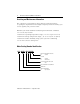
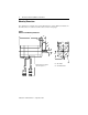
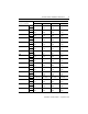
Connector Data
The tables below list the signal descriptions for the encoder and power
connector pins.
Encoder Connector Power Connector
Pin Signal Pin Signal
1 - 8, 25-28 Open 1
Phase R
1
9A+ 2
Phase S
1
10 A- 3
Phase T
1
11 B+ 4 Open
12 B- 5 Ground
13 I+ 6 Open
14 I- 7
Brake+
2
15 HALL A+ 8 Open
16 HALL A- 9
Brake-
2
17 HALL B+
1
Cables and drives may label the R, S and T
power phases as U, V and W respectively.
2
Open on non-brake motors.
18 HALL B-
19 HALL C+
20 HALL C-
21 Open
22 +5 VDC
23
COM
1
24
Shield
2
1
+5V COM not connected to motor case ground.
2
Cable Shield connected to motor case ground.
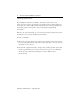
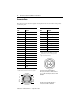
Power housing: AMP 206705-2
BR+, BR- pin contacts: AMP 66102-8
R, S, T and Ground pin contacts: AMP
66098-8
Encoder housing: AMP 206152-1
Pin contacts: AMP 3-66507-0
3
21
4 5 6
7 8
9
1
21 25
2826
3
4 8
9
14
2015