
Owner manual

Item Number 814036 - Rev C
2-20 Installation
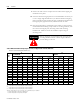
* Only one type thermal sensor will be supplied with the motor. Check model number to determine the
correct sensor.
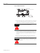
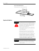
ATTENTION
!
• Disconnect input power supply before installing or
servicing motor
• Motor lead connections can short and cause damage or
injury if not well secured and insulated.
• Insulate the connections, equal to or better than the
insulation on the supply conductors.
• Properly ground the motor per selected drive manual.
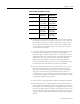
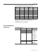
Table 2.Q Motor Feedback Cable (Hall/Thermal Signals
Standard Wiring Signal Type Color from
Module
Signal
Designation
Signal Spec
Trapezoidal
Hall
Effect
Circuit
Red +V 5-24Vdc Hall Supply, 20 mA
Black VRTN Hall signal common
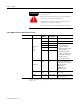
White S1 •Trapezoidal Hall Signals,
120
o
Spacing, Open
Collector Transistor
(24Vmax) Outputs (Pull-up
Resistor External)
•Consult drive manual or
supplier for specific wiring
instructions to the drive.
Wiring is phase/
commutation sensitive.
Blue S2
Orange S3
Thermistor*
Black
Black
TR+
TR-
Positive Temperature
Coefficient (PTC) thermistor
Design control circuit to trip at
130°C as necessary.
<300
Ω @ 25°C
<1500
Ω @ 125°C
>4000
Ω @ 135°C
Thermal Switch* Blue
Blue
TS+
TS-
Normally Closed Opens at
130°C, <1
Ω
Shield Silver Brad Cable Shield Terminate at drive end per drive
manual instructions