ANORAD LC Series Linear Motors USER MANUAL October 2006 Item Number 814036 Publication Number LC-UM001C-EN-P
i Important User Information Because of the variety of uses for the products described in this publication, those responsible for the application and use of this motor assembly must satisfy themselves that all necessary steps have been taken to assure that each application and use meets all performance and safety requirements, including any applicable laws, regulations, codes and standards.
Table of Contents Important User Information. . . . . . . . . . . . . . . . . . . . . . . . . . . . . . . . . . . . . . . . . . . . . . . . . . . . . . . . . . . . . . . . . i Introduction Using This Manual. . . . . . . . . . . . . . . . . . . . . . . . . . . . . . . . . . . . . . . . . . . . . . . . . . . . . . . . . . . . . . . . . . . . . . Product Description . . . . . . . . . . . . . . . . . . . . . . . . . . . . . . . . . . . . . . . . . . . . . . . . . . . . . . . . . . . . . . . . . . . . General .
iii Item Number 814036 - Rev C
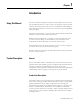
Chapter 1 Introduction Using This Manual This motor manual is designed to help you install, integrate and start-up your new Anorad Linear Motor. You do not have to be an expert in motion control. However, this manual does assume you have a fundamental understanding of basic electronics, mechanics, as well as motion control concepts and applicable safety procedures. The intent of this manual is to assist the user in the mechanical and electrical installation of the Anorad LC Series Linear Motor.
1-2 Introduction For servo drives that require commutation feedback, an optional trapezoidal (digital) Hall effect feedback module may be attached to the front of the motor coil. The LC may also be commutated via software. Anorad offers a full line of compatible servo controls and drives.
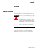
Chapter 2 Installation Unpacking and Inspection Inspect motor assemblies to make certain no damage has occurred in shipment. Any damage or suspected damage should be immediately documented. Claims for damage due to shipment are usually made against the transportation company. Also contact Anorad immediately for further advise. ATTENTION ! Linear Motors contain powerful permanent magnets which require extreme caution during handling.
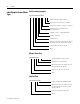
2-2 Installation Identifying the Linear Motor Coil Assembly (example) Type LC-030-100-D-0-T-TR-0 Special Configurations: Blank = Standard UL Rated: Blank = Not UL Rated; UL = UL Rated Cable Length: 0 = 300 mm; 1 = 600 mm; 2 = 1000 mm Thermal Sensor: TR = PTC Thermal Sensor; TS = Thermal Switch Feedback: 0 = none; T = Trapezoidal Hall Effect Cooling: 0 = No Cooling Winding Code: D, E Coil Length: 100 = 100 mm; 200 = 200 mm; 300 = 300 mm; 400 = 400 mm; 600 = 600 mm; 800 = 800 mm Frame Size: 030, 050, 075,
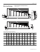
Installation Motor Layout Drawings 2-3 Figure 2.1 LC-30 Coil and Cooling Plate Drawing Dimensions mm [in] H G F 53.72 ±0.13 [2.115±0.005] E D 45.72 ±0.13 [1.800±0.005] OPTIONAL COOLING PLATE ASSEMBLY (Ø.25" TUBING) C B A 15.00 [0.591] 33.65 [1.325] 66.67 [2.625] 65.00 +1.00 0 [2.559 +0.039 ] -0.000 25.00 [0.984] L REF AIR GAP 1.22 ±0.42 [.045 ±0.16] 30.00 [1.181] OPTIONAL HALL EFFECT MODULE Ø6.0 [0.24] CABLE (FLYING LEADS) THERMISTOR CABLE Ø3.0 [0.
2-4 Installation Figure 2.2 LC-30 Magnet Channel Layout Drawing L +/- 0.25 [+/- 0.010] 24.50 [0.965] 60.00 [2.362] 50.00 [1.969] "N" PLACES 48.00 [1.890] 6.00 [0.236] 50.0 [1.969] MOUNTING HOLE DIMENSION Track #1 12.50 [0.492] Ø5.50 [0.216] THRU C'BORE Ø9.50 [0.375] X 5.0 [0.197] DP SEE CHART FOR QTY 13.26 ±0.16 [0.522±0.006] Track #2 Y +/- 0.08 [+/- 0.003] AIR GAP WILL RESULT FROM SETTING THE PLATES TO SETUP DIMENSION SHOWN 25.00 [0.984] SETUP DIMENSION 8.00 [0.315] +0.026 Ø3.988 -0.000 +0.
Installation 2-5 Figure 2.3 LC-50 Coil and Cooling Plate Drawing Dimensions mm [in] H G F E D C B A 25.00 [0.984] 33.65 [1.325] 66.67 [2.625] 85.00 +1.00 0 [3.346 +0.039 ] -0.000 30.00 [1.181] L X M5 X 0.8 X 15MM TOTAL DEPTH THREADS START 5MM DEEP 53.72 ±0.13 [2.115 ±0.005] 45.72 ±0.13 [1.800 ±0.005] OPTIONAL COOLING PLATE ASSEMBLY (Ø 0.25" TUBING) 30.00 [1.181] OPTIONAL HALL EFFECT MODULE Ø6.0 [0.24] CABLE (FLYING LEADS) THERMISTOR CABLE Ø3.0 [0.
2-6 Installation Table 2.C Coil and Cooling Plate Dimensions Coil Size L A B C D E F G 50 x 100 134.00 (5.28) 50 x 200 234.00 (9.21) 100.00 (3.937) 166.67 (6.562) 50 x 300 334.00 (13.15) 133.33 (5.249) 200.00 (7.874) 266.67 (10.499) 50 x 400 434.00 (17.09) 133.33 (5.249) 233.33 (9.186) 300.00 (11.811) 366.67 (14.436) 30 x 600 634.00 (25.31) 133.33 (5.249) 233.33 (9.186) 333.33 (13.123) 433.33 (17.060) 500.00 (19.686) 566.66 (22.310) 30 x 800 834.00 (32.84) 133.33 (5.
Installation 2-7 Figure 2.5 LC-75 Coil and Cooling Plate Drawing Dimensions mm [in] H F G E 110.0 +1.00 0 [4.33 +0.04 -0.00 ] D C 53.72 ±0.13 [2.115 ±0.005] 45.72 ±0.13 [1.800 ±0.005] B A 66.67 [2.625] OPTIONAL COOLING PLATE ASSEMBLY (Ø 0.25" TUBING) 33.6 [1.32 ] 30.0 [1.18] OPTIONAL HALL EFFECT MODULE Ø6.0 [0.24] CABLE (FLYING LEADS) THERMISTOR CABLE Ø3.0 [0.12] (FLYING LEADS) POWER CORD 4 COND SHIELDED SEE TABULATION (FLYING LEADS) 40.00 [1.575] 35.00 [1.378] M5 X 0.
2-8 Installation Table 2.E Coil and Cooling Plate Dimensions Coil Size L A B C 75 x 100 134.00 (5.28) 75 x 200 234.00 (9.21) 100.00 (3.937) 166.67 (6.562) 75 x 300 334.00 (13.15) 133.33 (5.249) 200.00 (7.874) 266.67 (10.499) 75 x 400 434.00 (17.09) 133.33 (5.249) 233.33 (9.186) 300.00 (11.811) 75 x 600 634.00 (25.31) 133.33 (5.249) 233.33 (9.1869) 75 x 800 834.00 (32.84) 133.33 (5.249) 233.33 (9.186) D E F G H Hole Qty (N) Flatness -A- 4 0.25 (0.010) 8 0.25 (0.
Installation 2-9 Figure 2.7 LC-100 Coil and Cooling Plate Drawing Dimensions mm [in] H G F E 53.72 ±0.13 [2.115 ±0.005] 45.72 ±0.13 [1.800 ±0.005] D C B A 33.65 [1.325] 66.67 [2.625] +1.00 135.00 0 ] [5.315 +0.039 -0.000 OPTIONAL COOLING PLATE ASSEMBLY (Ø 0.25" TUBING) REF AIR GAP 1.22 ±0.42 [0.045 ±0.16] 30.00 [1.181] OPTIONAL HALL EFFECT MODULE Ø 6.0 [0.24] CABLE (FLYING LEADS) THERMISTOR CABLE Ø 3.0 [0.12] (FLYING LEADS) 60.00 [2.362] 37.50 [1.476] L X M5 X 0.
2-10 Installation Table 2.G Coil and Cooling Plate Dimensions Coil Size L A B C D 100 x 100 134.00 (5.28) 100 x 200 234.00 (9.21) 100.00 (3.937) 166.67 (6.562) 100 x 300 334.00 (13.15) 133.33 (5.249) 200.00 (7.874) 266.67 (10.499) 100 x 400 434.00 (17.09) 133.33 (5.249) 233.33 (9.186) 300.00 (11.811) 100 x 600 634.00 (25.31) 133.33 (5.249) 233.33 (9.1869) 100 x 800 834.00 (32.84) 133.33 (5.249) 233.33 (9.186) E F G H Hole Qty (N) Flatness -A- 4 0.25 (0.010) 8 0.
Installation 2-11 Figure 2.9 LC-150 Coil and Cooling Plate Drawing Dimensions mm [in] H 185.00 +1.00 0 [7.283 +0.039 ] -0.000 G F E D C B A 61.72 ±0.13 [2.430 ±0.005] 49.72 ±0.13 [1.957 ±0.005] 33.65 [1.325] 30.00 [1.181] OPTIONAL HALL EFFECT MODULE Ø 6.0 [0.24] CABLE (FLYING LEADS) 66.67 [2.625] 120.00 [4.724] REF AIR GAP 1.22 ±0.42 [0.045 ±0.16] OPTIONAL COOLING PLATE ASSEMBLY (Ø 0.375" TUBING) 60.00 [2.362] 180.00 [7.087] THERMISTOR CABLE Ø 3.0 [0.12] (FLYING LEADS) 32.50 [1.
2-12 Installation Table 2.I LC-150 Coil and Cooling Plate Dimensions Coil Size L A B C D E F G 150 x 100 134.00 (5.28) 150 x 200 234.00 (9.21) 100.00 (3.937) 166.67 (6.562) 150 x 300 334.00 (13.15) 133.33 (5.249) 200.00 (7.874) 266.67 (10.499) 150 x 400 434.00 (17.09) 133.33 (5.249) 233.33 (9.186) 300.00 (11.811) 366.67 (14.436) 150 x 600 634.00 (25.31) 133.33 (5.249) 233.33 (9.186) 333.33 (13.123) 433.33 (17.060) 500.00 (19.686) 566.66 (22.310) 150 x 800 834.00 (32.
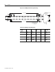
Installation 2-13 Figure 2.11 LC-200 Coil and Cooling Plate Drawing Dimensions mm [in] H +1.00 235.00 0 +0.039 [9.252 ] -0.000 G F E D C B 61.72 ±0.13 [2.430 ±0.005] 49.72 ±0.13 [1.957 ±0.005] A 33.65 [1.325] 66.67 [2.625] 150.00 [5.906] REF AIR GAP 1.22 ±0.42 [0.045 ±0.16] 30.00 [1.181] OPTIONAL HALL EFFECT MODULE Ø 6.0 [0.24] CABLE FLYING LEADS OPTIONAL COOLING PLATE ASSEMBLY (Ø 0.375" TUBING) 100.00 [3.937] 50.00 [1.969] 230.00 [9.055] THERMISTOR CABLE Ø 3.0 [0.12] (FLYING LEADS) 42.
2-14 Installation Table 2.K LC-200 Coil and Cooling Plate Dimensions Coil Size L A B C D E F G 200 x 100 134.00 (5.28) 200 x 200 234.00 (9.21) 100.00 (3.937) 166.67 (6.562) 200 x 300 334.00 (13.15) 133.33 (5.249) 200.00 (7.874) 266.67 (10.499) 200 x 400 434.00 (17.09) 133.33 (5.249) 233.33 (9.186) 300.00 (11.811) 366.67 (14.436) 200 x 600 634.00 (25.31) 133.33 (5.249) 233.33 (9.186) 333.33 (13.123) 433.33 (17.060) 500.00 (19.686) 566.66 (22.310) 200 x 800 834.00 (32.
Installation 2-15 Motor Storage Motor storage area should be clean, dry, vibration free and have a relatively constant temperature. The coil resistance measurement checks explained in this manual should be done at time of storage. If a motor is stored on equipment, it should be protected from the weather. All motor surfaces subject to corrosion should be protected by applying a corrosion resistant coating.
2-16 Installation Figure 2.14 Magnet Plate Installation 24.8 [ 0.97 ] 50.00 [ 1.969 ] N S N Ø5.50 [0.216] THRU C'BORE Ø 9.50 [0.374] X 5.0 [0.197] DP 50.00 [ 1.969 ] S N S N S ALIGNMENT TOOL 0.5 REF. [ 0.02 ] 6.0 [ 0.24 ] 12.5 [ 0. ] 25.00 [ 0.984 ] BUTTING PLATES [ +0.007 Ø 3.988 0 0.1570 +0.0003 -0.0000 ] HOLES FOR DOWEL PIN 1. Ensure the mounting surface to which the magnet plate is to be attached is clear of any and all foreign material.
Installation 2-17 Table 2.M Opening for Motor Assembly Motor with Cooling Plate without Cooling Plate LC-30 53.72 ± 0.13 (2.115 ± 0.005) 45.72 ± 0.13 (1.800 ± 0.005) LC-50 53.72 ± 0.13 (2.115 ± 0.005) 45.72 ± 0.13 (1.800 ± 0.005) LC-100 53.72 ± 0.13 (2.115 ± 0.005) 45.72 ± 0.13 (1.800 ± 0.005) LC-150 61.72 ± 0.13 2.430 ± 0.005) 49.72 ± 0.13 (1.957 ± 0.005) LC-200 61.72 ± 0.13 2.430 ± 0.005) 49.72 ± 0.13 (1.957 ± 0.005) 4.
2-18 Installation 9. Position the slide over the complete sections and continue aligning the remainder of the plates. 10. If the area where the magnet plates are to be installed does not allow you to use a straight edge describes above, an alternate method of aligning plates can be done. Space the plate by using a 0.020 plastic shim between the magnet plates, tighten the bolts, and then remove the shim. 11. Once all the alignment is completed, torque all bolts to values listed in the tables.
Installation 2-19 Table 2.O Recommended Seating Torques (Inch-Lb.) for Metric Bolts Bolt Size (Metric) Pitch Plain Cadmium Plated Zinc M1.6 0.35 2.6 1.95 3.64 M2 0.40 5.3 3.98 7.42 M2.5 0.45 11 8.25 15.4 M3 0.5 19 14.25 26.6 M4 0.7 41 30.75 57.4 M5 0.8 85 63.75 119 M6 1.0 140 105 196 M8 1.25 350 262.5 490 M10 1.5 680 510 1020 Grade 12.9 – ISO 898/1 Socket Head Cap Bolts (ANSI B1.
2-20 Installation ATTENTION ! • Disconnect input power supply before installing or servicing motor • Motor lead connections can short and cause damage or injury if not well secured and insulated. • Insulate the connections, equal to or better than the insulation on the supply conductors. • Properly ground the motor per selected drive manual. Table 2.
Installation Motor/Hall Phasing and Sequence 2-21 See Figure 2.15 for the standard phase and sequence relationship of the LC series motors when phased in the specific motor direction. The Trapezoidal Hall signals are used by a compatible three phase brushless servo drive to perform electronic commutation. Two types of servo drive Hall-based commutation techniques are possible, Trapezoidal Hall Mode and Encoder (Software/Digital) Mode with Trapezoidal Hall start-up.
2-22 Installation Figure 2.16 Positive Motor Direction When properly wired this is considered the positive direction Coil Motion Stationary M agnet Operational Guidelines ATTENTION ! Moving parts can injure. Before running the motor, make sure all components are secure and magnet mounting hardware is below magnet surface. Remove all unused parts from the motor travel assembly to prevent them from jamming in the motor air gap and damaging the coil or flying off and causing bodily injury.
Installation 2-23 Motor (Coil) Thermal Protection ATTENTION ! LC motors with the thermal protection option will supply a signal that indicates the motor temperature limit condition. This signal should be used by the motor control/drive system to immediately shut down the motor power on an open condition. Since linear motors are generally not repairable, and typically highly integrated into the mechanical structure, redundant motor thermal protection is strongly recommended. 1.
2-24 Installation Item Number 814036 - Rev C
Chapter 3 Troubleshooting Hall Effect/Thermal Signal Module Troubleshooting and Replacing Troubleshooting the module: ATTENTION ! Even with motor power disabled and leads disconnected, permanent magnet motors can generate high Back EMF voltage when moving due to external forces. 1. Thermal Sensor - Refer to thermal sensor signal specification on Table 2.R for resistance - temperature values. 2. Hall Effect Circuit - Hall Signals a.
3-2 Troubleshooting 3. Hall to Back EMF Phasing a. With drive power OFF, verify Hall circuit is connected to the drive per interface wiring specifications. b. Disconnect motor leads from drive. c. Turn Hall power supply ON (driver power ON). d. While slowly and steadily moving the motor by hand, perform the Hall signal test except this time check the motor phases are in-phase with the specific Hall signal per the Motor Phasing Diagram.
Troubleshooting Basic Motor Checks Electrical ATTENTION ! 3-3 Dangerous voltages, forces and energy levels exist in servo controlled systems. Extreme care must be exercised when operating, maintaining or servicing the linear motor to prevent harm to personnel or equipment Coil Resistance Measurements - Ohmmeter After installation is completed and before running for the first time, this procedure should be performed to ensure no damage occurred during installation.
3-4 Troubleshooting • Compare the phase resistance readings to the cold resistance specification of the specific coil model. If the three readings are balanced but much different than specified, the reason may be a special coil model or due the cable resistance (if much higher.) To rule out the cable resistance, disconnect the field cable at the coil assembly interface and repeat the procedures at the coil.
Troubleshooting 3-5 5. Repeat previous oscilloscope procedure comparing B-C to A-C. In this case A-C should lead B-C by 60o. The shapes and peak voltages should be approximately the same. Note that probe common = C. Pay attention to the specified phasing direction. Calculating the Back EMF Constant: 1. The Back EMF calculation is compared to the motor’s rated Back EMF constant.
3-6 Troubleshooting Mechanical displacement of one electrical cycle = motor magnetic pitch (180o) in inches multiplied by two. Note that the published specification may already be in “cycles.” In this case do not multiply by two. Calculate Back EMF constant: inches mechanical displacement of one cycle (inches) --------------------------------------------------------------------------------------------------------------= velocity [ ----------------- ] second cycle time (seconds) V ptz = V ( pK – pK ) × 0.
Troubleshooting 3-7 6. Slowly and steadily move the motor by hand in one direction over the whole travel. Monitor the waveshape as you are doing this. The Hall signal should alternate between a high and low (squarewave) DC level of equal duty cycle as the Hall module passes over the alternating polarity magnets. Especially at magnet plate joints, ensure the squarewave shape is consistent. Any changes or irregularities in the squarewave duty cycle shape may indicate a magnet polarity problem.
3-8 Troubleshooting Item Number 814036 - Rev C
Troubleshooting 3-9 Item Number 814036 - Rev C
Anorad/Rockwell Automation 100 Precision Drive Shirley, NY 11967-4710 Web site http://www.anorad.com E-mail anorad@anorad.com Technical Support: Tel (631) 344-6600 Fax (631) 344-6660 email techsupport@anorad.com Item Number 814036 - Rev C October 2006 1 © 2006 Rockwell Automation Printed in the U.S.A.