Installation Instructions HPK-Series Asynchronous Servo Motors Catalog Numbers HPK-B1307, HPK-E1307, HPK-B1308, HPK-E1308, HPK-B1310, HPK-E1310, HPK-B1609, HPK-E1609, HPK-B1611, HPK-E1611, HPK-B1613, HPK-E1613, HPK-B1815, HPK-E1815, HPK-B2010, HPK-E2010, HPK-B2212C, HPK-E2212C, HPK-B2510C Topic Page Important User Information 2 Motor Catalog Number Identification 3 Before You Begin 4 Installation and Maintenance Guidelines 4 Installing an HPK Motor 11 Product Dimensions 15 Motor Connectors 2
HPK-Series Asynchronous Servo Motors Important User Information Solid state equipment has operational characteristics differing from those of electromechanical equipment. Safety Guidelines for the Application, Installation and Maintenance of Solid State Controls, publication SGI-1.1, is available from your local Rockwell Automation sales office or online at http://www.rockwellautomation.com/literature.
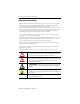
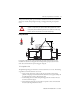
HPK-Series Asynchronous Servo Motors 3 Motor Catalog Number Identification HPK - B 1307 C- S A 4 2 A A FACTORY DESIGNATED OPTIONS A = Standard MOUNTING TYPE/SHAFT KEY A = IEC Metric, Free Mounting Holes (Type FF), Foot and Flange Mount, Keyed Shaft B = IEC Metric, Free Mounting Holes (Type FF), Foot Mount Only, Keyed Shaft BRAKE 2 = No Brake 4 = 380…460V ac Brake CONNECTORS 4 = Right-angle Rotatable BLOWER/JUNCTION BOX A = Inline Blower, F3 Jx Box B = Top-mount Blower, F1 Jx Box C = Top-mount Blower, F2
HPK-Series Asynchronous Servo Motors Before You Begin Before unpacking the product, inspect the shipping carton for damage. If damage is visible, immediately contact the shipper and request assistance. Otherwise, proceed with unpacking. Remove the motor carefully from its shipping container, and visually inspect the motor for any damage. Carefully examine the motor frame, front output shaft, and mounting pilot for any defects.
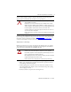
HPK-Series Asynchronous Servo Motors 5 Take precautions during a lift to prevent hazardous overload due to deceleration, acceleration, or shock forces caused by abrupt raising or lowering, or swinging and twisting of a suspended motor. ATTENTION: Eyebolts may unscrew during lifting. Prior to lifting, check the eyebolts to verify that they are tight and attach lifting equipment to restrict turning during the lift. Alternatively, lift the unit on a platform or with a sling.
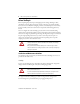
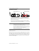
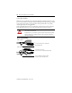
HPK-Series Asynchronous Servo Motors Cable Orientation for Drip Loop Cables enter from below. A drip loop is formed in each cable. Cables enter from above. Drip loops are not formed. • Brakes on these servo motors are holding brakes. The brakes are spring-set, and release when voltage is applied to the brake coil. A separate power source is required to disengage the brake. This power source may be applied by a servo motor controller, in addition to manual operator control.
HPK-Series Asynchronous Servo Motors 7 When mounting couplings or pulleys to the shaft, verify that the connections are properly aligned and that axial and radial loads are within the motor specifications. ATTENTION: Do not strike the shaft, key, couplings, or pulleys with tools during installation or removal. Damage may occur to the motor bearings and the feedback device if sharp impact to the shaft is applied during installation of couplings and pulleys, or a shaft key.
HPK-Series Asynchronous Servo Motors Allow sufficient clearances in the area of the motor for it to stay within its specified operating temperature range. Refer to Specifications for the operating range. Do not install the motor in an area with restricted airflow. Keep other heat producing devices away from the motor. IMPORTANT Sufficient clearance must be provided on all inlet and outlet openings to provide for unrestricted flow of air. Allow at least 152 mm (6.0 in.
HPK-Series Asynchronous Servo Motors 9 Interconnect Cables Knowledgeable cable routing improves system electromagnetic compatibility (EMC). Refer to Grounding of Signal Wire Shields Within a Cable for suggested cable trim lengths, and for cable shield grounding at the motor frame. IMPORTANT The recommended wire size is based on motor current requirements and terminal block sizing.
HPK-Series Asynchronous Servo Motors Power Cable Shielding HPK-Series motors with brakes integrate the brake signals (BR+ and BR-) with the 380…460V power at the terminal block. The separate shield surrounding the brake signals must be grounded to the overall system ground. To properly ground the brake ground shield, or any separately shielded signal, follow these wiring guidelines. Verify each cable shield connects to the overall chassis ground by routing as shown in diagram.
HPK-Series Asynchronous Servo Motors 11 Installing an HPK Motor Observe the following when installing an HPK-Series motor. ATTENTION: Do not strike the shaft, couplings, or pulleys with tools during installation or removal. Damage may occur to the motor bearings and the feedback device if sharp impact to the shaft is applied during installation of couplings and pulleys. Failure to observe these procedures could result in damage to the motor and its components. 1.
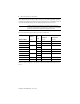
HPK-Series Asynchronous Servo Motors 6. Route power cables into the junction box. The recommended wire size is based on motor current requirements and terminal block sizing. Consult your local electrical code before selecting wire gauge for your application. IMPORTANT The table lists the access hole diameters for the junction box, and the maximum width of the wire terminal inside the junction box. Motor Catalog No. HPK-x1307, HPK-x1308, HPK-x1310 Dia. A, Max. Dia. B, Max.
HPK-Series Asynchronous Servo Motors 13 7. Connect the power cable leads (U/T1, V/T2, and W/T3) to the power terminals. 8. Connect the ground and shield connect to the ground lug. AC Input to Motor Connect Input with Wire Color to Terminal M8 Clamping Bolt Torque M6 Cover Threaded Bolt Torque Line 1 Black U/T1 14 N•m (1.6 lb-in.) 8 N•m (0.9 lb-in.) Line 2 Blue V/T2 Line 3 Brown W/T3 Ground Green/Yellow GND Shield Yellow/Green 9.
HPK-Series Asynchronous Servo Motors Blower Wiring Diagrams DELTA T6 T4 T1 STAR T5 T2 L1 L2 T3 L3 Low Volts Line W2 U2 U1 L1 L2 T4 T5 T1 T2 T3 L1 L2 L3 High Volts Line V2 V1 T6 W1 L3 Low Volts Line W2 U2 V2 U1 V1 W1 L1 L2 L3 High Volts Line U1 = Black V1 = Blue W1 = Brown U2 = Green V2 = White W2 = Yellow 11.
HPK-Series Asynchronous Servo Motors 15 Product Dimensions The figures show dimension symbols for the HPK-Series motors, and these dimensions are provided in tables. Motors are designed to metric dimensions. Inch dimensions are approximate conversions from millimeters. Dimensions without tolerances are for reference. TIP HPK-Series Motor (Non-brake) Dimensions (HPK-B/E13xx and HPK-B/E16xx) Junction box rotates in 90° increments. F3 mount (top) location is shown.
HPK-Series Asynchronous Servo Motors HPK-Series Motor (Non-brake) Dimensions (HPK-B/E13xx and HPK-B/E16xx) Motor Series A AA AB AC B B1 B2 BA HPK-B/E mm (in.) mm (in.) mm (in.) mm (in.) mm (in.) mm (in.) mm (in.) mm (in.) 1307 216 (8.50) 108 (4.25) 260 (10.2) 279 (10.9) 333 (13.1) 365 (14.3) 390 (15.3) 154 (6.06) 1308 371 (14.6) 403 (15.8) 428 (16.8) 1310 403 (15.8) 435 (17.1) 462 (18.1) N/A 414 (16.3) 452 (17.8) 1611 N/A 464 (18.2) 502 (19.
HPK-Series Asynchronous Servo Motors 17 HPK-Series Motor (Non-brake) Dimensions (HPK-B/E13xx and HPK-B/E16xx) Motor Series EA F G GA H HB HC HD HPK-B/E mm (in.) mm (in.) mm (in.) mm (in.) mm (in.) mm (in.) mm (in.) mm (in.) 1307 52.0 (2.05) 13.9 (0.55) 42.4 (1.67) 51.3 (2.02) 366 (14.4) 53.0 (2.09) 262 (10.3) 132 (5.20) 52.0 (2.05) 16.0 (0.63) 48.5 (1.91) 58.7 (2.31) 444 (17.4) 62.0 (2.44) 316 (12.4) 160 (6.30) 1308 1310 1609 1611 450 (17.
HPK-Series Asynchronous Servo Motors HPK-Series Motor (Brake) Dimensions (HPK-B/E13xx and HPK-B/E16xx) LD Airflow Clearance Required Encoder Connector J1 B B1 L AD AE AF H Junction box rotates in 90° increments. F1 mount (left side) location is shown. F2 mount (right side) is available.
HPK-Series Asynchronous Servo Motors 19 HPK-Series Motor (Brake) Dimensions (HPK-B/E13xx and HPK-B/E16xx) Motor Series AD AE AF BE H J1 J2 L LD HPK-B/E mm (in.) mm (in.) mm (in.) mm (in.) mm (in.) mm (in.) mm (in.) mm (in.) mm (in.) 1307 247 (9.72) 236 (9.29) 195 (7.68) 298 (11.7) 588 (23.1) 190 (7.48) 196 (7.72) 888 (34.9) 336 (13.2) 1308 336 (13.2) 926 (36.4) 1310 368 (14.5) 957 (37.7) 1609 285 (11.2) 236 (9.29) 225 (8.86) 328 (12.9) 670 (26.3) 224 (8.
HPK-Series Asynchronous Servo Motors HPK-Series Motor (Non-brake) Dimensions (HPK-B/E1815 and HPK-B/E2010) Airflow Clearance Required Junction box rotates in 90° increments F3 mount (top) location is shown. Encoder Connector BD BC BB C B BA E L EA Shaft Diameter Tolerance HPK-B1815 HPK-E1815 motors: Ø 70.007...70.033 (2.7562...2.7572) HPK-B2010 HPK-E2010 motors: Ø 80.007...80.033 (3.1500...3.
HPK-Series Asynchronous Servo Motors 21 HPK-Series Motor (Non-brake) Dimensions (HPK-B/E1815 and HPK-B/E2010) Motor Series A AB AC B BA BB BC BD HPK-B/E mm (in.) mm (in.) mm (in.) mm (in.) mm (in.) mm (in.) mm (in.) mm (in.) 1815 279 (10.9) 350 (13.8) 382 (15.1) 622 (24.5) 670 (26.4) 420 (16.5) 174 (6.85) 476 (18.7) 2010 318 (12.5) 397 (15.6) 403 (15.9) 654 (25.7) 705 (27.7) 420 (16.5) 203 (8.0) 450 (17.7) Motor Series C1 D E EA F G GA H HPK-B/E mm (in.
HPK-Series Asynchronous Servo Motors HPK-Series Motor (Brake) Dimensions (HPK-B/E2010) LD Airflow Clearance Required Encoder Connector J1 L HPK-x2010x-x44BA is shown AD AE H Junction box rotates in 90° increments. F1 mount (left side) location is shown. F2 mount (right side) is available. J2 HPK-Series Motor (Brake) Dimensions (HPK-B/E2010) Motor Series AD AE H L HPK-B/E mm (in.) mm (in.) mm (in.) mm (in.) mm (in.) 2010 484 (19.0) 360 (14.2) 725 (28.5) 1245 (49.0) 330 (13.
HPK-Series Asynchronous Servo Motors 23 HPK-Series Motor (Non-brake) Dimensions (HPK-B2212C and HPK-B2510C) Junction box rotates in 90° increments F3 mount (top) location is shown. Encoder Connector BD Airflow Clearance Required BC BB C B BA E L EA Shaft Diameter Tolerance HPK-B2212 motor: Ø 60.010...60.030 (2.3626...2.3624) HPK-B2510 motor: Ø 80.007...80.033 (3.1500...3.
HPK-Series Asynchronous Servo Motors HPK-Series Motor (Non-brake) Dimensions (HPK-B2212C and HPK-B2510C) Motor Series A AB AC B BA BD C D HPK-B mm (in.) mm (in.) mm (in.) mm (in.) mm (in.) mm (in.) mm (in.) mm (in.) 2212 356 (14.0) 445 (17.5) 476 (18.7) 806 (31.7) 864 (34.0) 588 (23.1) 156 (6.13) 60 (2.36) 2510 406 (16.0) 497 (19.6) 533 (21.0) 775 (30.5) 838 (33.0) 695 (27.4) 162 (6.4) Motor Series E EA F G GA H HB HC HPK-B mm (in.) mm (in.) mm (in.
HPK-Series Asynchronous Servo Motors 25 HPK-Series Motor (Brake) Dimensions (HPK-B2212C) LD Airflow Clearance Required Encoder Connector L HPK-B2212C-SB44BA is shown AD AE H Junction box rotates in 90° increments. F1 mount (left side) location is shown. F2 mount (right side) is available. HPK-Series Motor (Brake) Dimensions (HPK-B2212C) Motor Series AD AE H L LD HPK-B/E mm (in.) mm (in.) mm (in.) mm (in.) mm (in.) 2212 521 (20.5) 396 (15.6) 816 (32.1) 1372 (54.0) 383 (15.
HPK-Series Asynchronous Servo Motors Motor Connectors The tables below contains connector and terminal block descriptions for the feedback connector, and the combined HPK-Series power and brake connector.
HPK-Series Asynchronous Servo Motors 27 Load Force Capacities This section contains the radial and axial motor load-force ratings for HPK-Series motors. These motors are capable of operating with the maximum radial or maximum axial shaft loads listed in the following tables. Radial loads listed are applied in the middle of the shaft extension.
HPK-Series Asynchronous Servo Motors Axial Load-force Ratings (Zero Radial Load) Motor Series 850 rpm 1150 rpm 1750 rpm 2500 rpm HPK- kg (lb) kg (lb) kg (lb) kg (lb) B/E1307 260 (572) 240 (528) 210 (462) 180 (396) B/E1308 260 (572) 240 (528) 210 (462) 180 (396) B/E1310 260 (572) 240 (528) 210 (462) 180 (396) B/E1609 360 (796) 330 (726) 290 (638) 250 (550) B/E1611 360 (796) 330 (726) 290 (638) 250 (550) B/E1613 360 (796) 330 (726) 290 (638) 250 (550) B/E1815 440
HPK-Series Asynchronous Servo Motors 29 Troubleshooting and Maintenance Standard troubleshooting and maintenance of this motor requires completion of these tasks: • • • • Bearing inspection Bearing greasing and repacking Periodic lubrication of a motor Shaft key removal and installation BURN HAZARD: Outer surfaces of the motor can reach high temperatures during motor operation. Take precautions to prevent accidental contact with hot surfaces.
HPK-Series Asynchronous Servo Motors 6. If possible, manually rotate the shaft at least three revolutions to distribute grease within the bearings before starting the motor. Periodic Lubrication of HPK-x1815…HPK-x2510 Motors The HPK-x1815, HPK-x2010, HPK-x2012, HPK-x2212, and HPK-x2510 motor design has a positive lubrication system for routing new grease directly into the bearing.
HPK-Series Asynchronous Servo Motors 31 Lubrication Amounts and Intervals The tables below list the recommended amount and interval for lubrication of HPK-Series motors. Chevron SRI-2 or equivalent grease is recommended, unless the motor nameplate specifies a special grease. Catalog Number Volume HPK-B or HPK-E Cubic Centimeter 1307…1815 Lubricated for life 2010, 2212 or 2510 Weight Cubic Inches Grams Ounces 32 2.0 28 1.
HPK-Series Asynchronous Servo Motors Shaft Key Removal and Installation Shaft keys are dimensioned for an interference fit, slightly larger than the opening. An interference fit provides a secure and rigid mating connection. ATTENTION: Do not strike the shaft, key, couplings, or pulleys with tools during installation or removal. Damage may occur to the motor bearings and the feedback device if sharp impact to the shaft is applied during installation of couplings and pulleys, or a shaft key.
HPK-Series Asynchronous Servo Motors 33 6. Verify the motor shaft, faceplate, bearing bore, wear sleeve, and keyway are free of nicks, burrs, grooves, or spiral machine marks. IMPORTANT Check the motor shaft and surrounding surfaces. Remove any nicks, burrs, or surface damage. Motor Cables and Accessory Kits Accessories available from the factory include motor feedback cables. Motor Cables Factory-manufactured feedback cables are available in standard cable lengths.
HPK-Series Asynchronous Servo Motors Additional Resources For additional information about motors and compatible Rockwell Automation drives, refer to these publications.
HPK-Series Asynchronous Servo Motors 35 Notes: Publication HPK-IN001C-EN-P - June 2010
Rockwell Automation Support Rockwell Automation provides technical information on the Web to assist you in using its products. At http://www.rockwellautomation.com/support/, you can find technical manuals, a knowledge base of FAQs, technical and application notes, sample code and links to software service packs, and a MySupport feature that you can customize to make the best use of these tools.