
Quick Reference Guide Manual
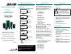


Power Wiring
Input Voltage: Determined by model
number. Voltage Class configures the
drive for International voltage supplies.
Control Wiring
Default: (Out-of-the-box) configuration is
for Keypad control. The user will be able
to start the controller using the built-in
drive mounted operator interface module.
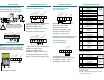
Control Wiring (cont.)
Two Wire Start/Stop Control
Logic Source Sel (89) = Terminal Block
Digital ln1 Sel (361) = Not Used
Digital ln2 Sel (362) = Run
Digital ln3 Sel (363) = Function Loss
Three Wire Start/Stop Control
Logic Source Sel (89) = Terminal Block
Digital ln1 Sel (361) = Stop
Digital ln2 Sel (362) = Start
Digital ln3 Sel (363) = Function Loss
See Digital lnx Sel (parameters 361 to
366) for configuration of all logic inputs.
Reference Wiring
Analog Reference Wiring
(0 to 10 VDC Input)
Speed Ref A Sel (90) = Analog ln 1
Speed Ref Hi (91) = 60 Hz.
Speed Ref Lo (92) = 0 Hz.
Analog ln Config (320) = .xx00
Analog ln 1 Hi (322) = 10.0 V
Analog ln 1 Lo (323) = 0.0 V
Analog Inputs can be configured for 4 - 20
mA. See instruction manual D2-3540.
Analog Output Wiring
(0 to 10 VDC Output)
Analog Out Absolute (341) = 1
Analog Out1 Sel (342) = Output Freq.
Analog Out1 Hi (343) = 10.0 V
Analog Out1 Lo (344) = 0.0 V
.
Terminal Assignments
Encoder Connections
(1) Z channel can be used as a pulse input while A and B
are used for encoder.
Publication D2-3544
Copyright © 2004 Rockwell Automation. All rights
reserved. Printed in USA.
!
ATTENTION: The GV6000
does not provide branch circuit
protection. The user must install
the proper protection devices.
U (T1)
V (T2)
W (T3)
R (L1)
S (L2)
T (L3)
PE
SHLD
BR1
BR2
DC+
DC -
U (T1)
V (T2)
W (T3)
PE
R (L1)
S (L2)
T (L3)
M
Increase/Decrease Speed
Start
Stop
24
25 26
L
o
g
i
c
C
o
m
.
S
u
p
p
l
y
C
o
m
.
F
u
n
c
t
i
o
n
L
o
s
s
+
2
4
V
D
C
29
24
2925 26 27 28
Logic
Com.
S
uppl
y Com.
R
un
Fun
c
tion Loss
+
24
V
DC
24
2925 26 27 28
Logic Com.
Su
p
ply Co
m
.
Start
Func
t
i
on
Lo
s
s
+2
4
V
D
C
Sto
p
2225
A
n
alog
I
n
1
(-)
C
om
m
on
+
10
VDC
A
na
l
og In 1
(
+
)
1
3
84567
A
O
u
t
V
o
l
t
s
C
o
m
m
o
n
-+
# Signal Default
1 Analog ln 1 (-) Depends
on params 320
- 327
2 Analog ln 1 (+)
3 Analog ln 2 (-)
4 Analog ln 2 (+)
5 Pot Common -
6 Analog Out 1 (-) Depends
on params 340
- 347
7 Analog Out 1 (+)
8 Analog Out 2 (-)
9 Analog Out 2 (+)
10 HW PTC Input 1 -
11 Digital Out 1 NC Fault
12 Digital Out 1 Common
13 Digital Out 1 NO NOT Fault
14 Digital Out 2 NC NOT Run
15 Digital Out 2/3 Common
16 Digital Out 3 NO Run
17 Analog ln Jumper -
Analog ln 1
18
19 Analog ln Jumper -
Analog ln 2
20
21 -10V Pot Reference -
22 +10V Pot Reference -
23 HW PTC Input 2 -
24 +24 VDC -
25 Digital ln Common -
26 24V Common -
27 Digital ln 1 Stop-CF
28 Digital ln 2 Start
29 Digital ln 3 Function Loss
30 Digital ln 4 Jog
31 Digital ln 5 Auto/Man.
32 Digital ln 6/Hardware Enable Speed Sel 1
No. Description
8 +12 VDC Power Internal Power
source 250 mA
7 +12 VDC Common
6 Encoder Z (NOT) Pulse marker
or registration
input
(1)
5 Encoder Z
4 Encoder B (NOT) Quadruple B
input
3 Encoder B
2 Encoder A (NOT) Single channel
or quadruple A
input
1 Encoder A