
User Manual


Installation Instructions
Optional
Communications
Module
L2L1T3T2T1 L3
INPUTOUTPUT
USE 75 C
COPPER WIRE
ONLY
TORQUE
52 IN-LB
(6 N-M)
BR2
PS+
PS–
BR1 DC+ DC–
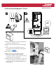
USE 75 C COPPER WIRE ONLY, TORQUE 52 IN-LB (6 N-M)
22-10
AWG
5.3 IN-LB
(0.6 N-M)
WIRE STRIP
2
0V
0V
DC–DC+
Fan/Fan Transformer Replacement – Frame 6
1
L1 L2 L3
O
I
=
A. Remove the screws that secure the right-side drive
enclosure panel. Remove panel.
B. Remove the screws that secure the terminal block
rail.
C. Gain access to the four transformer screws by
repositioning the terminal block rail and terminal
label sheet. See Figure 1
.
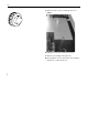
D. Disconnect transformer wires.
E. Remove the screws securing the transformer.
Remove the transformer. If the transformer
incorporates a jumper, note placement and correctly
position jumper on new transformer.
F. Position and secure new transformer to chassis with
screws previously removed. Re-assemble drive in
reverse order. All screws should be tightened to 3.2
N-m (28 lb.-in.).
Figure 1