
User Manual Instruction Manual

6-8
GV6000 AC Drive User Manual
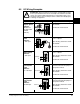
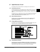
Analog Input
PTC
PTC OT set > 5V
PTC OT
cleared<4V
PTC Short < 0.2V
Set Fault Config 1 (238) to bit 7 =
Enabled.
Set Alarm Config 1 (259) to bit 11 =
Enabled.
HW PTC Input
PTC OT set > 5V
PTC OT
cleared<4V
PTC Short < 0.2V
Set Fault Config 1 (238) to bit 13 =
Enabled.
Set Alarm Config 1 (259) to bit 18 =
Enabled
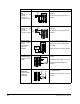
Analog Output
+/- 10V, 4-20mA
Bipolar,
+10V Unipolar
(shown in
example)
Configure with parameter 340.
Select Source Value: Digital Out1
Sel (384)
Adjust Scaling: parameters 343/344
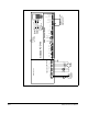
2-Wire
1
Control
Non-Reversing
24V DC internal
supply
Set Digital Input 1 (361) to 0 =
Unused.
Set Digital Input 2 (362) to 7 = Run.
Set Direction Mode (190) to 0 =
Unipolar.
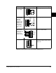
2-Wire
1
Control
Reversing
External supply
(I/O Board
dependent)
Set Digital Input 1(361) to
8 = Run Forward.
Set Digital Input 2 (362) to 9 = Run
Reverse.
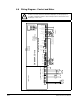
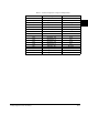
Input/Output Connection Example Required Parameter Changes
5
3.32k
Ohm
1.8k
PTC
Ferrite
Bead
1
2
22
1.8k
PTC
Ferrite
Bead
10
23
6
7
+–
24
25
26
28
Stop-Run
25
27
28
Run Rev.
Run Fwd.
115V/
+24V
Neutral/
Common