
User Manual Instruction Manual

6-4
GV6000 AC Drive User Manual
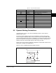
Important: Terminals 24 & 26 are utilized onluy on 24VDC I/O Boards. They are not
to be used on 115VAC I/O Boards. 115VAC control power must be
provided by user for 115VAC I/O Boards.
Important: *Factory installed jumpers exist between terminals 24 & 29 and between
terminals 25 & 26 on the 24 VDC Logic Board only. The jumpers are not
present on the 115 VAC Logic Board. The user is responsible for the
removal of one or both of these jumpers in order to implement an external
function loss circuit.
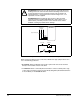
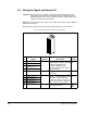
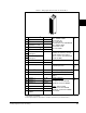
6.3 Wiring the Encoder Terminal Block
Wire the drive’s encoder terminal block as shown in table 6.2.
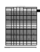
3.Differential Isolation - External source must be maintained at less than 160V with respect to PE. Input
provides high common mode immunity.
4.Contacts in unpowered state. Consists of 3 relay (dry contact) outputs. Digital Out 1 consists of 1N.O./1
N.C. contact, Digital Out 2 consists of 1 N.C. and Digital Out 3 consists of 1 N.O. contact. Digital Out 2 & 3
share a common terminal (terminal 15). Any relay programmed as Fault or Alarm will energize (pick up)
when power is applied to drive and deenergize (drop out) when a fault or alarm exists. Relays selected for
other functions will energize only when that condition exists and will deenergize when condition is removed.
5.150mA maximum load. Not present on 115V versions.
6.See section 6.4 for more information on hardware enable.
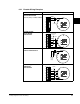
Table 6.2 – Wiring Encoder Terminal Block
No. Description (See Appendix A for Encoder Specifications.)
8 +12 VDC Power Internal power source 250mA.
7 +12 VDC Return (Common)
6 Encoder Z (NOT)
Pulse marker or registration input.
1
1.Z channel can be used as a pulse input while A and B are used for encoder.
5 Encoder Z
4 Encoder B (NOT) Quadrature B input.
3 Encoder B
2 Encoder A (NOT) Single channel or quadrature A input.
1 Encoder A
8
1