
User Manual Instruction Manual
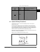
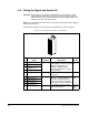
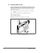

Installing Regulator Board Control Wiring
6-3
11
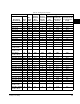
Digital Out 1 - N.C.
4
Fault Max. Resistive Load: 240 VAC/30
VDC - 1200VA, 150W
Max Current: 5A
Min. Load: 10mA
Max Inductive Load: 240 VAC/30
VDC - 840VA, 105W
Max Current: 3.5 A
Min Load: 10mA
380 -
391
12 Digital Out 1 Common
13
Digital Out 1- N.O.
4
NOT Fault
14
Digital Out 2 - N.C.
4
NOT Run
15 Digital Out 2/3 Com.
16
Digital Out 3 - N.O.
4
Run
17
Current ln Jumper
1
-
Analog ln 1
Placing a jumper across
terminals 17 and 18 (or 19 and
20) will configure that analog
input for current. (Parameter 320
must be set ON.)
320
18
19
Current ln Jumper
1
-
Analog ln 2
20
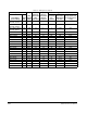
21 -10V Pot Reference - 2k ohm minimum load.
22 +10V Pot Reference -
23 HW PTC Input 2 - 1.8k ohm PTC, internal 3.32k
ohm pull-up resistor
18, 238,
211,
259
24*
+24 VDC
5
-
Drive supplied logic input power.
5
25* Digital ln Common -
26*
24V Common
5
- Common for internal power
supply.
5
27 Digital ln 1 Stop-CF 115VAC, 50/60 Hz -
Opto isolated
Low State: less than 30 VAC
High State: less than 100VAC
24VDC
- Opto Isolated
Low State: less than 50VDC
High State: greater than 20VDC
11.2 mA DC
361 -
366
28 Digital ln 2 Start
29* Digital ln 3 Function
Loss
30 Digital ln 4 Jog
31 Digital ln 5 Auto/Man.
32 Digital ln 6/Hardware
Enable
6
Speed Sel 1
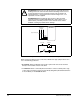
1.Important: 4-20mA operation requires a jumper at terminals 17 and 18 (or 19 and 20). Drive damage may
occur if jumper is not installed.
2.These inputs/outputs are dependent on a number of parameters (see Related Params).
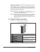
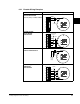
Table 6.1 – Wiring Signal and Control I/O to the Terminal Block
1
16
32