
User Manual Instruction Manual

6-2
GV6000 AC Drive User Manual
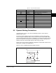
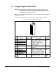
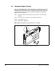
6.2 Wiring the Signal and Control I/O
Important: Two I/O boards are available: 24 VDC logic and 115 VAC logic. Verify
which board is installed in the drive before wiring the signal and control
I/O terminal block. This can be verified by the drive’s model number or by
a label on the side of the I/O Cassette.
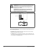
Note: If the 115 VAC logic board is used, the 115 VAC control power must be supplied
separately by the user.
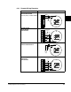
Wire the drive’s signal and control I/O to the terminal block as shown in table 6.1.
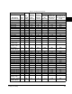
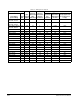
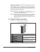
Table 6.1 – Wiring Signal and Control I/O to the Terminal Block
No. Signal
Factory
Default Description
Related
Param.
1
Analog ln 1 (-)
12
Isolated
3
, bipolar, differential, +/-
10V/4-20mA, 11 bit plus sign, 88k
ohm input impedance. For
4-20mA, a jumper must be
installed at terminals 17 and 18
(or 19 and 20).
320 -
327
2
Analog ln 1 (+)
1
3
Analog ln 2 (-)
1
4
Analog ln 2 (+)
1
5 Pot Common - For (+) and (-) 10V pot
references.
6 Analog Out 1 (-)
2
Bipolar (current output is not
bipolar), +/- 10V/4-20mA, 11 bit
plus sign, voltage mode-limit
current to 5 mA. Current mode -
max load resistance is 400 ohms.
340 -
347
7 Analog Out 1 (+)
8 Analog Out 2 (-)
9 Analog Out 2 (+)
10 HW PTC Input 1 - 1.8k ohm PTC, internal 3.32k
ohm pull-up resistor
18, 211,
238,
259
1
16
32