
User Manual Instruction Manual

Installing Power Wiring
5-7
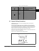
5.5 Dynamic Braking Connections
A dynamic brake consists of the 7th internal braking transistor and an optional
dynamic brake resistor.
The internal dynamic braking circuit senses rising DC bus voltage and shunts the
excess energy to the dynamic brake resistor. The 7th transistor is either ON or OFF,
connecting the dynamic brake resistor to the DC bus, or isolating the resistor from the
DC bus. It is important to properly size the braking resistor value. To determine the
minimum resistance value possible based on drive rating, see table
Note that the resistor wattage is application-dependent and should be sized to inertia,
deceleration, and duty cycle requirements.
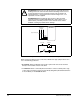
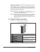
Figure 5.3 shows a simplified dynamic braking schematic.
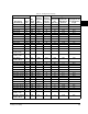
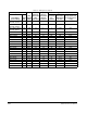
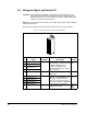
Table 5.3 – Power Terminal Descriptions
Terminal Description Notes
BR1 DC Brake Dynamic brake resistor connection (+)
BR2 DC Brake Dynamic brake resistor connection (–)
DC+ DC Bus (+) DC bus connection (+)
DC– DC Bus (–) DC bus connection (–)
U U (T1) Output to Motor
V V (T2) Output to Motor
W W (T3) Output to Motor
1
1. Frame 2 only.
Ground
PE
1
PE Ground Earth Ground
R R (L1) AC line input power
S S (L2) AC line input power
T T (L3) AC line input power
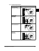
Figure 5.3 – Simplified Dynamic Braking Schematic
BR1
BR2
+DC Bus
-DC Bus
Dynamic Braking
Resistor
Chopper
Transistor
Chopper Transistor
Voltage Control
To Voltage Dividers