
User Manual Instruction Manual


Installing Power Wiring
5-1
CHAPTER 5
Installing Power Wiring
This chapter provides instructions on output wiring to the motor and installing AC input
power wiring. See figure 2.4 for terminal block locations.
5.1 Removing and Replacing the Cover
Follow these steps to open the drive cover:
Frames 0 -4
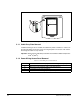
Step 1. Locate the slot in the upper left hand corner of the drive (see figure 5.1).
Step 2. Slide the locking tab up and swing the door open. The hinges allow the cover
to move away from the drive and lay on top of adjacent drive (if present).
Refer to section 5.1.2 for information on access panel removal.
Frame 5
Step 1. Locate the slot in the upper left hand corner of the drive (see figure 5.1).
Step 2. Slide the locking tab up, loosen the right-hand cover screw and remove.
Refer to section 5.1.2. for information on access panel removal.
Frame 6
Step 1. Loosen two screws at bottom of drive cover.
Step 2. Carefully slide bottom cover down and out.
Step 3. Loosen two screws at top of cover and remove.
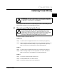
!
ATTENTION: The user is responsible for conforming with all applicable
local and national codes. Failure to observe this precaution could result
in damage to, or destruction of, the equipment.
!
ATTENTION: DC bus capacitors retain hazardous voltages after input
power has been removed. After disconnecting input power, wait five
minutes for the DC bus capacitors to discharge and then check the
voltage with a voltmeter to ensure the DC bus capacitors are discharged
before touching any internal components. Failure to observe this
precaution could result in severe bodily injury or loss of life.