
User Manual Instruction Manual

4-8
GV6000 AC Drive User Manual
Initially, the cable is in a fully charged condition. A transient disturbance occurs by
discharging the cable for approximately 4 ms. The propagation delay between the
inverter terminals and motor terminals is approximately 1 ms. The small time between
pulses of 4 ms does not provide sufficient time to allow the decay of the cable
transient. Thus, the second pulse arrives at a point in the motor terminal voltage’s
natural response and excites a motor overvoltage transient greater than 2 pu.
The amplitude of the double pulsed motor overvoltage is determined by a number of
variables. These include the damping characteristics of the cable, bus voltage, and the
time between pulses, the carrier frequency, modulation technique, and duty cycle.
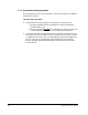
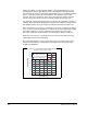
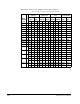
Figure 4.3 shows the per unit motor overvoltage as a function of cable length. This is
for no correction versus the modulation correction code for varied lengths of #12 AWG
PVC cable to 600 feet for a 4 kHz and 8 kHz carrier frequencies. The output
line-to-line voltage was measured at the motor terminals in 100 feet increments.
Without the correction, the overvoltage increases to unsafe levels with increasing
cable length for both carrier frequencies.
The patented modulation correction code reduces the overvoltage for both carrier
frequencies and maintains a relatively flat overvoltage level for increasing cable
lengths beyond 300 feet.
Figure 4.3 – Motor Overvoltage as a Function of Cable Length
No Correction vs Correction Method at 4 kHz and 8 kHz Carrier
Frequencies - Vbus = 650, fe = 60 Hz
Cable Length (Feet)
per Unit Vout/Vbus
1.6
1.7
1.8
1.9
2
2.1
2.2
2.3
2.4
2.5
2.6
1000 200 400 600300 500
No Correction 4 kHz Carrier
Corrected 4 kHz Carrier
No Correction 8 kHz Carrier
Corrected 8 kHz Carrier