
User Manual Instruction Manual

Wiring Requirements for the Drive
4-7
4.4.1 Reflected Wave Compensation
You must understand the effects and restrictions when applying the drive to extended
motor lead length applications. Proper cable type, motor and drive selection is
required to minimize the potential risks.
The reflected wave phenomenon, also known as transmission line effect, produces
very high peak voltages at the motor terminals due to voltage reflection. Voltages in
excess of twice the DC bus voltage, (650 V DC nominal @480 V input) result at the
motor and can cause motor winding failure.
While Reliance Electric drives have patented software that limits the voltage peak to 2
times the DC bus voltage and reduce the number of occurrences, many motors have
inadequate insulation systems to tolerate these peaks.
The correction software modifies the PWM modulator to prevent PWM pulses less
than a minimum time from being applied to the motor. The minimum time between
PWM pulses is 10 microseconds. The modifications to the PWM modulator limit the
overvoltage transient to 2.25 per unit volts line-to-line peak at 600 feet of cable.
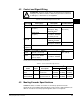
• 400 V Line = 540V DC bus (max) x 2.25 = 1200 V
• 480 V Line = 715V DC bus (max) x 2.25 = 1600 V
• 600 V Line = 891V DC bus (max) x 2.25 = 2000 V
Parameter 56 is used to enable or disable this feature. Refer to the parameter
description in chapter 11 for more information.
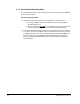
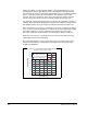
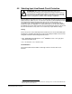
Figure 4.2 shows the inverter line-to-line output voltage (top trace) and the motor
line-to-line voltage (bottom trace) for a 10 HP, 460 V AC inverter, and an unloaded 10
HP AC induction motor at 60 Hz operation. 500 ft. of #12 AWG PVC cable connects
the drive to the motor.
Figure 4.2 – Inverter and Motor Line-to-Line Voltages
<T
α
1670 V
pk
5010152025
Time (msec)
30 35 40 45 50
500
V/div
0
500
V/div
Inverter
Motor
0