
User Manual Instruction Manual

Wiring Requirements for the Drive
4-5
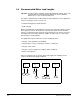
4.2 Control and Signal Wiring
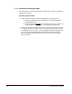
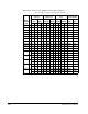
4.3 Meeting Encoder Specifications
GV6000 AC drives can utilize an encoder for closed loop operation. Encoder
specifications are provided in table A.6. Drives set up for V/Hz or SVC regulation can
utilize an encoder for closed loop speed regulation, but it is not required.
!
ATTENTION: Verify the voltage rating of the I/O Interface board before
wiring any user devices. Failure to observe this precaution could result
in damage to, or destruction of, the equipment.
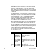
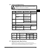
Table 4.2 – Recommended Signal and Control Wire
Signal Type Wire Type(s) Description
Minimum
Insulation Rating
Recommended Signal Wire
Analog I/O Belden 8760/9460
(or equiv.)
0.750 mm
2
(18 AWG),
twisted pair, 100%
shield with drain
1
.
1.If the wires are short, contained within a cabinet and are not mixed with noisy circuits, the use of shielded
wire may not be necessary, but is always recommended.
300V, 75-90° C
(167-194
°F)
Belden 8770
(or equiv.)
0.750 mm
2
(18 AWG)
3-conductor, shielded
for remote pot only.
Encoder/
Pulse I/O
Belden 9728 (or equiv.)
0.196 mm
2
(24 AWG),
individually shielded.
0.750 mm
2
(18 AWG),
twisted pair, shielded.
EMC
Compliance
Refer to EMC Compliance in Section 2.4.
Recommended Control Wire for Digital I/O
Unshielded
Control
Per US NEC or applicable
national or local code
-300V,
60
°C (140°F)
Shielded
Control
Multi-conductor shielded
cable such as Belden
8770 (or equiv.)
0.750 mm
2
(18 AWG),
3-conductor, shielded.
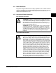
Table 4.3 – Control Terminal Block Specifications
Name Frame Description
Wire Size Range
1
1.Maximum/minimum sizes that the terminal block will accept. These are not recommendations.
TorqueMax Min
I/O Terminal
Block
All Signal & Control
Connections
2.1mm
(14 AWG)
0.3 mm
(22 AWG)
0.6 N-m
(5.2 in-lb)
Encoder
Terminal Block
All Encoder Power &
Signal Connections
0.75 mm
(18 AWG)
0.196 mm
(24 AWG)
0.6 N-m
(5.2 in-lb)