
User Manual Instruction Manual


3-16
GV6000 AC Drive User Manual
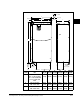
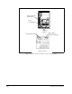
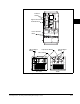
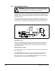
Figure 3.8 – Wire Routing and Terminal Block Locations (Frame 2 Shown)
BR1 B
SHLD SHLD
V/T2 W/T3 PE R/L1 S/L2 T/L3
AUX IN+ AUX OUT–
Optional
Communications
Module
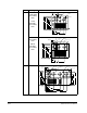
75C Cu Wire
6 AWG [10MM
2
] Max.
12 IN. LBS.
1.4 N-M
} TORQUE
WIRE
STRIP
CONTROL
POWER
Signal and Control
Terminal Block
Power
Terminal Block
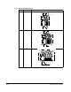
I/O and Signal Wiring
Input Power Wiring
Motor Wiring
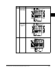
Ter mi n al
Shield
(Frame 2 shown)