
User Manual Instruction Manual
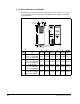

Mounting the Drive, Grounding, and Determining Wire Routing Locations
3-7
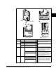
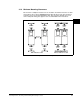
3.1.3 Minimum Mounting Clearances
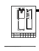
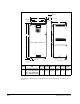
Be sure there is adequate clearance for air circulation around the enclosure. For best
air movement, do not mount GV6000 AC drives directly above each other. Note that
no devices are to be mounted behind the drive. This area must be kept clear of all
control and power wiring. See figure 3.3 for recommended air flow clearances.
Figure 3.3 – Minimum Mounting Clearances
101.6 mm
(4.0 in.)
101.6 mm
(4.0 in.)
50.8 mm
(2.0 in.)
101.6 mm
(4.0 in.)
101.6 mm
(4.0 in.)
PWR
RDY
DRIVE
MS
NET A
NET B
PWR
RDY
DRIVE
MS
NET A
NET B
101.6 mm
(4.0 in.)
101.6 mm
(4.0 in.)
101.6 mm
(4.0 in.)
101.6 mm
(4.0 in.)
PWR
RDY
DRIVE
MS
NET A
NET B
PWR
RDY
DRIVE
MS
NET A
NET B
With Adhesive Label
Without Adhesive Label