
User Manual Instruction Manual

Mounting the Drive, Grounding, and Determining Wire Routing Locations
3-5
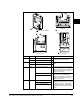
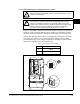
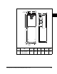
3.1.1.4 Selecting/Verifying Fan Voltage (Frames 5 & 6 Only)
Frames 5 and 6 utilize a transformer to match the input line voltage to the internal fan
voltage. If your line voltage is different than the voltage class specified on the drive
nameplate, it may be necessary to change transformer taps as shown in figure 3.2.
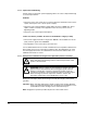
Common Bus (DC input) drives require user supplied 120 or 240 V AC to power the
cooling fans. The power source is connected between “0 VAC” and the terminal
corresponding to your source voltage. See Figure 2.4 and Table 2.7 for the terminal
block location and Figure 5.2 for the terminal layout.
!
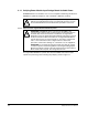
ATTENTION: Ensure that all power to the drive has been removed
before performing the following. Failure to follow this precaution could
result in a shock hazard.
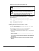
!
ATTENTION: DC bus capacitors retain hazardous voltages after input
power has been removed. After disconnecting input power, wait five
minutes for the DC bus capacitors to discharge and then check the
voltage with a voltmeter to ensure the DC bus capacitors are discharged
before touching any internal components. Failure to observe this
precaution could result in severe bodily injury or loss of life.
Table 3.1 – Fan VA Ratings (DC Input Only)
Frame Rating (120V or 240V)
5 100 VA
6 138 VA
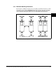
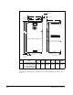
Figure 3.2 – Typical Locations - Phase Select Jumper and Transformer (Frame 5 Shown)
LINE
TYPE
SPARE 1
SPARE 2
3-PH 1-PH
480 Volt Tap
600 Volt Tap
690 Volt Tap
400 Volt Tap
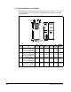
WIRE RANGE: 14-1/0 AWG (2.5-35 MM
2
)
TORQUE: 32 IN-LB (3.6 N-M)
STRIP LENGTH: 0.67 IN (17 MM)
USE 75 C CU WIRE ONLY
POWER TERMINAL RATINGS
WIRE RANGE: 6-1/0 AWG (16-35 MM
2
)
TORQUE: 44 IN-LB (5 N-M)
STRIP LENGTH: 0.83 IN (21 MM)
GROUND TERMINAL RATINGS (PE)
300 VDC EXT PWR SPLY TERM (PS+, PS-)
WIRE RANGE: 22-10 AWG (0.5-4 MM
2
)
TORQUE: 5.3 IN-LB (0.6 N-M)
STRIP LENGTH: 0.35 IN (9 MM)
17
21
INPUT ACOUTPUT
Optional
Communications
Module
9