
User Manual Instruction Manual
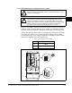

Mounting the Drive, Grounding, and Determining Wire Routing Locations
3-3
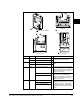
Frames Jumper Component No. Action
0-1 PEA Common Mode Capacitors
❶
Remove the I/O Cassette. Jumpers
located on the Power Board.
PEB MOV’s
➋
2-4 PEA Common Mode Capacitors
➌
Jumpers located above the Power Terminal
Block.
PEB MOV’s
➍
5 Wire Common-Mode Capacitors
➎
Remove the I/O Cassette. The green/yellow
jumper is located on the back of chassis.
Disconnect, insulate and secure the wires to
guard against unintentional contact with
chassis or components.
MOV’s
➏
Note location of the two green/yellow jumper
wires next to the Power Terminal Block.
Disconnect, insulate and secure the wires to
guard against unintentional contact with
chassis or components.
Input Filter Capacitors
6 Wire Common-Mode Capacitors
Remove the wire guard from the Power
Terminal Block. Disconnect, the three green
/yellow wires from the two “PE” terminals.
Insulate/secure the wires to guard against
unintentional contact with chassis or compo-
nents.
MOV’s
Input Filter Capacitors
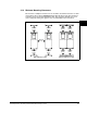
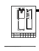
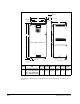
Figure 3.1 – Typical Jumper Locations
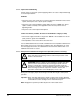
BR1 BR2 DC+ DC- U/T1 V/T2 W/T3
SHLD SHLD
PE R/L1 S/L2 T/L3
PE 2
MOV-PE JMPR
PE 1
AUX IN+ AUX OUT–
75C Cu Wire
6 AWG [10MM
2
] Max.
12 IN. LBS.
1.4 N-M
} TORQUE
WIRE
STRIP
CONTROL
POWER
PE 4
PE 3
DC FILTER CAP-PE JMPR
Frame 2
Frame 5
BR1 BR2 DC+ DC- U/T1 V/T2 W/T3 R/L1 S/L2 T/L3
PE B
PE A
75C Cu Wire
3 AWG [25MM
2
] Max.
16 IN. LBS.
1.8 N-M
} TORQUE
WIRE
STRIP
CONTROL
POWER
AUX IN
+ –
SHLD
SHLD
PE
75C Cu Wire
6 AWG [10MM
2
] Max.
BR1 BR2
12 IN. LBS.
1.4 N-M
} TORQUE
WIRE RANGE: 14-1/0 AWG (2.5-35 MM
2
)
TORQUE: 32 IN-LB (3.6 N-M)
STRIP LENGTH: 0.67 IN (17 MM)
USE 75° C CU WIRE ONLY
POWER TERMINAL RATINGS
WIRE RANGE: 6-1/0 AWG (16-35 MM
2
)
TORQUE: 44 IN-LB (5 N-M)
STRIP LENGTH: 0.83 IN (21 MM)
GROUND TERMINAL RATINGS (PE)
300 VDC EXT PWR SPLY TERM (PS+, PS-)
WIRE RANGE: 22-10 AWG (0.5-4 MM
2
)
TORQUE: 5.3 IN-LB (0.6 N-M)
STRIP LENGTH: 0.35 IN (9 MM)
17
21
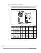
INPUT ACOUTPUT
Optional
Communications
Module
9
Frames 3 & 4
B
R
1
B
R
2
D
C
+
D
C
–
P
E
U
/
T
1
V
/T
2
W
/T
3
R
/L
1
S
/L
2
T
/L
3
U
s
e
7
5
C
W
i
r
e
O
n
l
y
#
1
0
-
#
1
4
A
W
G
T
o
r
q
u
e
t
o
7
i
n
-
l
b
s
!
D
A
N
G
E
R
➎
➏
Frames 0 and 1