
User Manual Instruction Manual

Application Notes
13-97
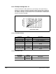
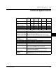
13.35.3 Example Configuration #3
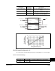
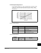
In this configuration Analog In 2 is a –10V to +10V signal which corresponds to –800%
to +800% motor torque from another drive. We want to use the –200% to +200%
range (–2.5V to +2.5V) of that motor torque and correspond it to –100% to +100% of
the PI Reference.
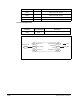
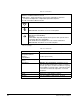
13.35.3.1 Parameter Settings
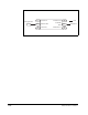
13.35.3.2 Parameter Settings
-100
-2.5
-1.5
-0.5
0.5
1.5
2.5
-80 -60 -40 -20 0 20 40 60 80 100
PI Reference
Scale1 In Value =
Analog In2 Value (Volts)
Parameter Value Description
Scale 1 In Hi (477) 2.5 V 2.5 V = 200% torque from other drive
Scale 1 In Lo (478) –2.5V –2.5 V = –200% torque from other drive
PI Reference Sel
(126)
25, Scale Block1
Out
The PI Reference becomes the output of
the scale block
PI Reference Hi
(460)
100 % 100% PI Reference corresponds to 200%
torque from other drive
PI Reference Lo
(461)
–100 % –100% PI Reference corresponds to
–200% torque from other drive
Destination
Parameter Source Parameter Description
Scale1 In Value
(476)
Analog In2 Value
(17)
We are scaling Analog In 2 value