
User Manual Instruction Manual

Application Notes
13-95
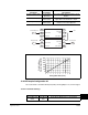
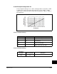
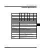
13.35.2 Example Configuration #2
Set a scale block to send Encoder Speed (415) to Analog Output 1 as a 0-10 V signal.
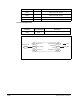
13.35.2.1 Parameter Settings
Scale2 In Value (482) Commanded
Speed (2)
Use Commanded Speed as Input to Scale
Block 2
Scale1 Out Hi (479) Scale2 Out
Value (487)
Use the output of Scale Block 2 to set the
upper limit of Scale Block 1 output
Preset Speed (101) Scale 1 Out
Value (481)
Use the scaled analog input as the trim
reference into Preset Speed 1
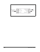
Destination
Parameter
Source
Parameter Description
483
482
484
2
485
486
479
101
480
477
476
478
2
481
487
Commanded Speed
Scale2 In Hi Scale2 Out Hi
Scale2 In Value
Scale2 Out Lo
Scale2 Out
Value
Preset Speed 1
= Link
Analog In2 Value
Scale2 In Lo
Scale1 In Hi Scale1 Out Hi
Scale1 In Value
Scale1 Out Lo
Scale1 Out
Value
Scale1 In Lo
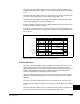
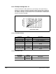
0
0
300
600
900
1200
1500
1800
12 34 56 7 8910
Analog Out1 Value (Volts)
Scale1 In Value =
Encoder Speed (RPM)
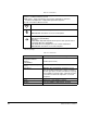
Parameter Value Description
Analog Out1 Sel
(342)
Scale Block1
Out
Scale Block1 Output goes to Analog Out1