
User Manual Instruction Manual

13-94
GV6000 AC Drive User Manual
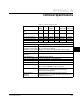
13.35.1 Example Configuration #1
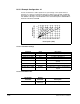
Use the scale blocks to add a speed trim as a percentage of the speed reference
instead of as a percent of full speed. Analog In 2 will be used to provide a 0-10V DC
trim signal. For example, when the commanded speed is 800 RPM, the maximum trim
with 10V DC at Analog In 2 will be 80 RPM. If the commanded speed is 1800 RPM the
maximum trim will be 180 RPM.
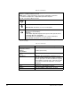
13.35.1.1 Parameter Settings
13.35.1.2 Parameter Links
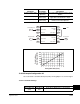
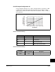
Cmd Spd = 400 RPM
Cmd Spd = 800 RPM
Cmd Spd = 1200 RPM
Cmd Spd = 1800 RPM
0
0
2
4
6
8
10
20 40 60 80 100 120 140 180
Preset Speed 1 (RPM)
Scale1 In Value =
Analog In2 Val (Volts)
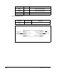
Parameter Value Description
Trim In Select (117) 11, Preset 1 Preset 1 becomes the trim speed
Scale1 In Hi (477) 10.0 V Hi value of Analog In 2
Scale1 In Lo (478) 0 V Lo value of Analog In 2
Scale1 Out Lo (480) 0 RPM Lo value of desired Trim
Scale2 In Hi (483) 1800 RPM Hi value of Commanded Speed (Max
Speed)
Scale2 In Lo (484) 0 RPM Lo value of Commanded Speed
Scale2 Out Hi (485) 180 RPM 10% of Max Speed
Scale2 Out Lo (486) 0 RPM Corresponds to lo value of Commanded
Speed
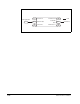
Destination
Parameter
Source
Parameter Description
Scale1 In Value (476) Analog In2
Value (17)
We are scaling Analog In 2 for our trim