
User Manual Instruction Manual

Application Notes
13-91
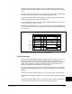
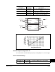
The power loss alarm in Drive Alarm 1 (211) is set and the power loss timer starts.
The Alarm bit in Drive Status 1 (209) is set if the Power Loss bit in Alarm Config 1(259)
is set.
The drive faults with a F003 – Power Loss fault if the power loss timer exceeds Power
Loss Time (185) and the Power Loss bit in Fault Config 1(238) is set.
The drive faults with a F004 – UnderVoltage fault if the bus voltage falls below Vmin
and the UnderVoltage bit in Fault Config 1(238) is set.
If the bus voltage rises above Vrecover for 20mS, the drive determines the power loss
is over. The power loss alarm is cleared.
If the drive is coasting and if it is in a “run permit” state, the reconnect algorithm is run
to match the speed of the motor. The drive then accelerates at the programmed rate to
the set speed.
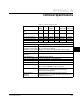
480 V example shown. See Table 13-7 for more information.
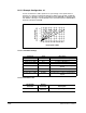
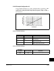
13.34.7 Coast Input
This mode can provide additional ride through time by sensing the power loss via an
external device that monitors the power line and provides a hardware power loss
signal. This signal is then connected to the drive through the “pulse” input (because of
its high-speed capability). Normally this hardware power loss input will provide a
power loss signal before the bus drops to less than Vopen.
The drive determines a power loss has occurred if the “pulse” input is de-energized
OR the bus voltage drops below Vopen. If the drive is running, the inverter output is
disabled.
The Power Loss alarm in Drive Alarm 1 (211) is set and the power loss timer starts.
The Alarm bit in Drive Status 1 (209) is set if the Power Loss bit in Alarm Config 1(259)
is set.
The drive faults with a F003 – Power Loss fault if the power loss timer exceeds Power
Loss Time (185) and the Power Loss bit in Fault Config 1 (238) is set.
680V
620V
560V
305V
365V
Bus Voltage
Motor Speed
Output Enable
Power Loss
Drive Fault
Pre-Charge